Oil lubricating structure

a technology of oil lubrication and oil pan, which is applied in the direction of lubrication for crankcase compression engines, lubrication check valves, machines/engines, etc., can solve the problems of insufficient oil supply to the first motor-generator and power split device, and the oil amount in the oil pan may drastically decreas

Inactive Publication Date: 2009-04-30
TOYOTA JIDOSHA KK +1
View PDF7 Cites 42 Cited by
  • Summary
  • Abstract
  • Description
  • Claims
  • Application Information

AI Technical Summary

Benefits of technology

[0013]Accordingly, the invention provides an oil lubricating structure capable of inhibiting air from being drawn in through the in

Problems solved by technology

If this happens, the amount of oil in the oil pan may drastically decrease such that air may be drawn into hydraulic equipment, such as an oil pump or

Method used


Image

  • Oil lubricating structure
  • Oil lubricating structure
  • Oil lubricating structure

Examples


Embodiment Construction

[0024]Example embodiments of the present invention will be described in greater detail below with reference to the accompanying drawings.

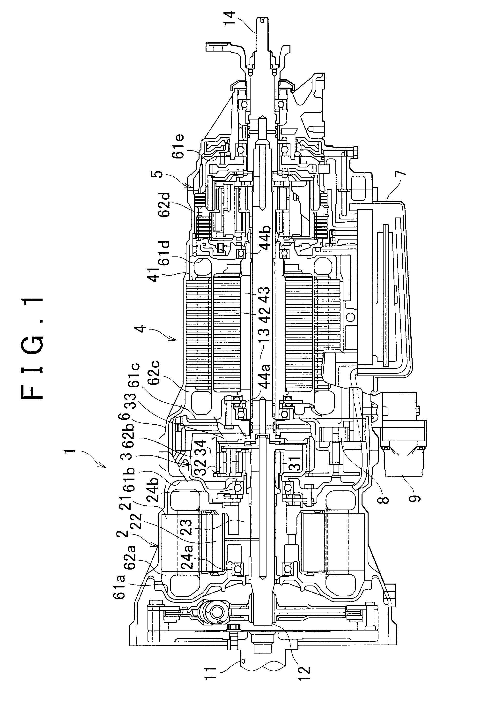
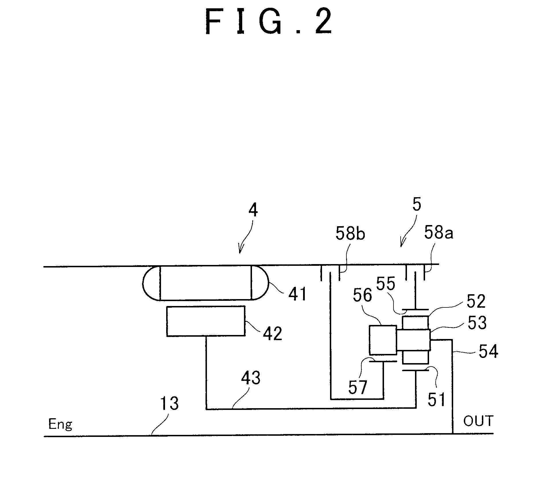
[0025]FIGS. 1 to 5D are views of a first example embodiment of the oil lubricating structure of the invention, and show an example in which the invention is applied to a hybrid vehicle drive apparatus.

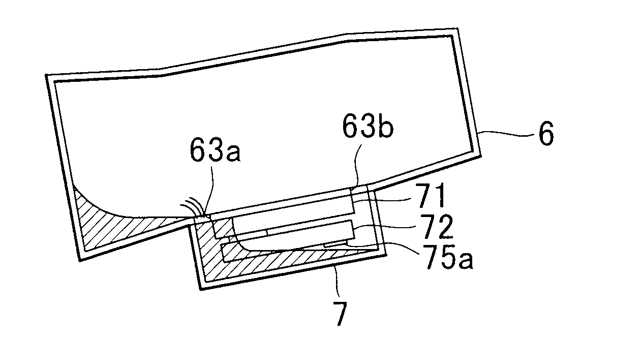
[0026]First the structure will be described. As shown in FIG. 1, a hybrid vehicle drive apparatus 1 is a two-motor type hybrid vehicle drive apparatus. The front end portion shown on the left side of the drawing is connected to an engine, not shown, via a crankshaft 11, and the rear end portion shown on the right side of the drawing is connected to a propeller shaft, also not shown. The hybrid vehicle drive apparatus I has a first motor-generator 2, a power split device 3, a second motor-generator 4, and a shift apparatus 5, all of which are elements requiring a supply of oil that are housed inside a case 6 which serves as the main body case. The firs...


PUM


Abstract

An oil lubricating structure includes a main body case having a housing chamber in which an element requiring a supply of oil is housed, an oil reservoir which is provided below the main body case and has an oil chamber in which oil collects, an oil supply portion which has an inlet port through which oil is drawn in from the oil chamber and which supplies oil collected in the oil chamber to the element requiring a supply of oil through the inlet port, and a duct member provided in the oil chamber. An oil return hole is provided which is formed in a bottom surface of the main body case toward the front of the oil reservoir and through which oil returns to the oil reservoir from the main body case. One end portion of the duct member is connected to the oil return hole and the other end portion of the duct member is positioned farther to the rear than the inlet port.

Description

INCORPORATION BY REFERENCE[0001]The disclosure of Japanese Patent Application No. 2007-280376 filed on Oct. 29, 2007, including the specification, drawings and abstract is incorporated herein by reference in its entirety.BACKGROUND OF THE INVENTION[0002]1. Field of the Invention[0003]The invention relates to an oil lubricating structure, and more particularly, to an oil lubricating structure suitable for supplying oil drawn in from an oil reservoir to an element requiring a supply of oil, and then returning the oil to the oil reservoir again.[0004]2. Description of the Related Art[0005]Typically in an oil lubricating structure of a vehicle such as an automobile, an oil pan which serves as an oil reservoir is attached to a lower portion of a main body case of a transmission. Oil collected in the oil pan is drawn up by an oil pump through an inlet port formed in a strainer and supplied to elements requiring a supply of oil, such as transmission gears that make up part of the transmiss...

Claims


Application Information

Patent Timeline
IPC IPC(8): F16N23/00F16N31/02F16H57/02F16H57/04F16N7/38F16N31/00
CPCB60K1/02B60K6/365B60K6/405B60K6/445B60K6/547Y02T10/6239F16H57/0424F16H57/0443F16H57/0445F16H57/0476F16H57/0484F16H57/0404Y02T10/62
Inventor SATO, AKIHIROMOTOIKE, KAZUTOSHIMATSUSHITA, JUNJI
Owner TOYOTA JIDOSHA KK
Why Eureka
Try Eureka