
Image tracking device, imaging device, image tracking method, and imaging method

Active Publication Date: 2009-04-30
MAXELL HLDG LTD
View PDF5 Cites 11 Cited by
  • Summary
  • Abstract
  • Description
  • Claims
  • Application Information

AI Technical Summary

Benefits of technology

[0013]According to a seventh aspect of the present invention, in the image tracking device of the fifth aspect, the controller may prevent the second focus detection for that focus detection position, among the plurality of focus detection positions, for which the focusing state was obtained when performing the first focus detection.
[0014]According to an eighth aspect of the present invention, in the image tracking device of the first aspect, the controller may prevent the second focus detection if recognition by the recognizer of the position of the image corresponding to the reference information has not been possible.
[0027]According to a 21st aspect of the present invention, in the image tracking method of the nineteenth aspect, the second focus detection may be prevented for that focus detection position, among the plurality of focus detection positions, for which the focusing state was obtained when the first focus detection is performed.
[0028]According to a 22nd aspect of the present invention, in the image tracking method of the fifteenth aspect, the second focus detection may be prevented if recognition of the position of the image corresponding to the reference information has not been possible.

Problems solved by technology

With the above described prior art auto focus system, it is not possible to start the focus detection calculation until the image information that is needed for calculation for tracking the photographic subject is obtained, since the focus detection calculation for the photographic lens is performed based upon the tracking calculation result for the photographic subject.
Accordingly if the calculation processing time period for each photograph is limited, as for example during sequential shooting or the like, then it is not possible to perform efficient control within this limited calculation processing time period.

Method used


Image

  • Image tracking device, imaging device, image tracking method, and imaging method
  • Image tracking device, imaging device, image tracking method, and imaging method
  • Image tracking device, imaging device, image tracking method, and imaging method

Examples


Embodiment Construction

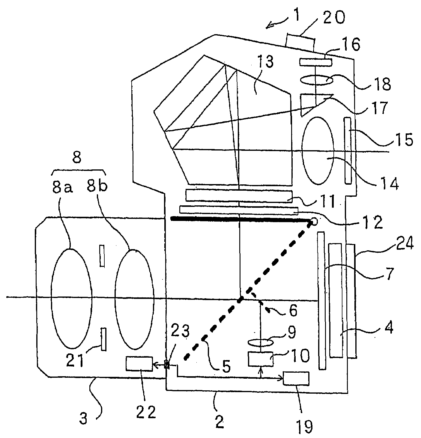
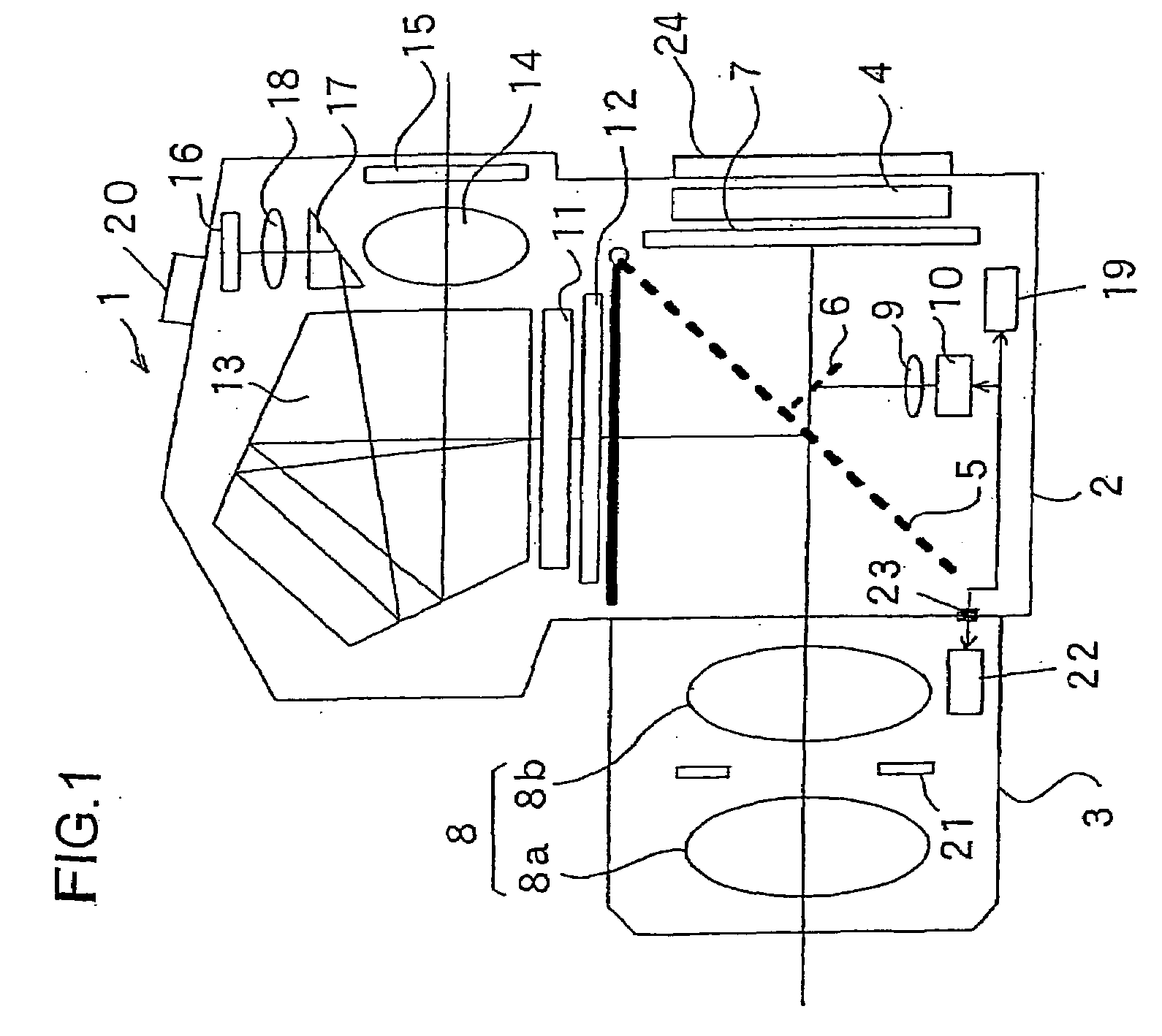
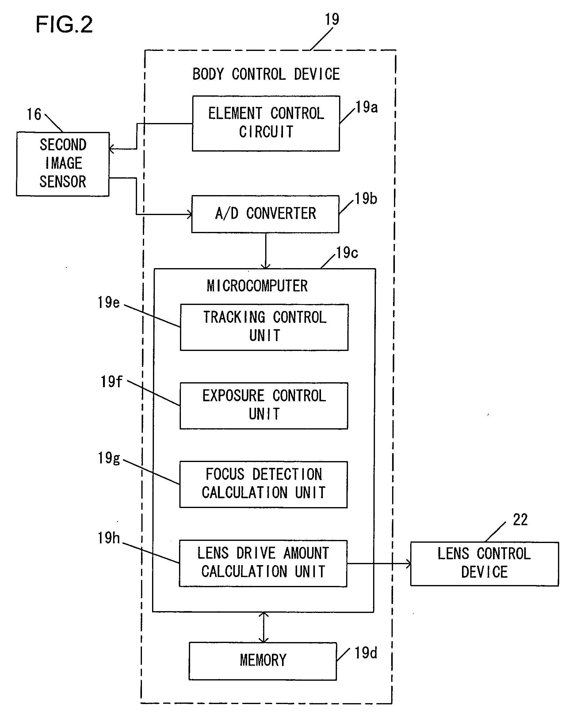
[0048]An image tracking device according to an embodiment of the present invention will now be explained in the following. The image tracking device of this embodiment stores reference information related to an image that is to be taken as a reference, takes an image created by an imaging optical system, and outputs image information. And, in the image that corresponds to the image information, an image that corresponds to the reference information is taken as a subject, and the position of this subject image within the photographic scene is recognized and is tracked. At this time, it is arranged to detect the focusing state of the imaging optical system before recognizing the position of the subject image, and, after having recognized the position of the subject image, to detect the focusing state of the imaging optical system for this position.

[0049]FIG. 1 is a figure showing the structure of an imaging device 1 (a single lens reflex digital still camera) that includes an image tr...


PUM


Abstract

An image tracking device comprises an image pickup device that takes an image formed by an imaging optical system and outputs image information, a focus detector that detects a focusing state of the imaging optical system, a recognizer that stores reference information related to a reference image and recognizes a position of an image corresponding to the reference information, within an image corresponding to the image information, and a controller that performs first focus detection in which the focusing state is detected by the focus detector, before the position is recognized by the recognizer, and second focus detection in which the focusing state is detected for the position that has been recognized by the recognizer.

Description

INCORPORATION BY REFERENCE[0001]This non-provisional application claims the benefit of U.S. Provisional Application No. 60 / 996,096 filed Nov. 1, 2007. This application also claims priority from Japanese Application No. 2007-283310 filed Oct. 31, 2007. The disclosure of each of the earlier applications is incorporated herein by reference in its entirety.BACKGROUND OF THE INVENTION[0002]1. Field of the Invention[0003]The present invention relates to an image tracking device, an imaging device, an image tracking method, and an imaging method.[0004]2. Description of Related Art[0005]The following type of auto focus system is known. In this auto focus system, there are provided an automatic focus adjustment (AF) function with which the defocus amounts of a photographic lens are obtained for a plurality of focus detection areas that are set within its photographic scene, and focus adjustment of the photographic lens is performed based upon the defocus amount of any one of these areas, and...

Claims


Application Information

Patent Timeline
IPC IPC(8): H04N5/232
CPCG03B13/36H04N5/23212G03B19/12H04N23/672H04N23/675H04N23/635
Inventor TAKEUCHI, HIROSHIOHNISHI, NAOYUKI
Owner MAXELL HLDG LTD
Learn More