
Sound in a conference communication session

Inactive Publication Date: 2009-04-30
SONY ERICSSON MOBILE COMM AB
View PDF8 Cites 5 Cited by
  • Summary
  • Abstract
  • Description
  • Claims
  • Application Information

AI Technical Summary

Benefits of technology

[0007]Embodiments of present invention may provide improved communications by realizing the possibilities that exist in the cellular phone field, in which network communication devices are often provided with short range communication abilities. In this field, accessories to such devices may also be provided with short range communication abilities. Phones, as well as many such accessories, are also provided with sound receiving capabilities. According to the present invention, such capability may be put to use in improving the sound transmitted in a conference communication session from one site to another.
[0033]Embodiments if the invention may provide various advantages. For example, it may be possible to combine and transfer sound from the various satellite communication devices. This sound may have a better quality than the sound picked up by a central microphone of the first main communication device, since microphones of the satellite communication devices may be held closer to the mouths of their users. This enables conferees at the second site to better hear what is being said at the first site. The invention can furthermore be provided without special conference equipment. It can use existing cellular phone technology. The units that are required for implementing the present invention normally exist in today's cellular phones and accessories to such phones. Therefore, additional costs for implementing the present invention are minimal.

Problems solved by technology

Under the above circumstances, it may be difficult to pick up the sound clearly from each of the participants at the first site, which means that the conferees at the second site, communicating with the first site over the communication network, may have difficulties in hearing what is being said.
This can lead to misunderstandings and reduce the efficiency of such conferences, which may be highly undesirable.

Method used


Image

  • Sound in a conference communication session
  • Sound in a conference communication session
  • Sound in a conference communication session

Examples


Embodiment Construction

[0042]The present invention is directed to providing a better quality of sound transmitted from a first site to a second site in a conference communication session.

[0043]Such sessions may being established via a communication network, which may include a computer network (e.g., using VoiP), a PSTN network, a wireless network, or any other suitable network over which conference communication sessions transmitting and receiving audio data can be conducted.

[0044]In an exemplifying description of the present invention this network will be a wireless wide area network (WAN), for example, a GSM network, a GPRS network, a CDMA network, a UMTS network, an LTE network, or other network. These are merely examples of networks where the present invention may be implemented. Thus, other communication networks can be used according to the principles of the present invention.

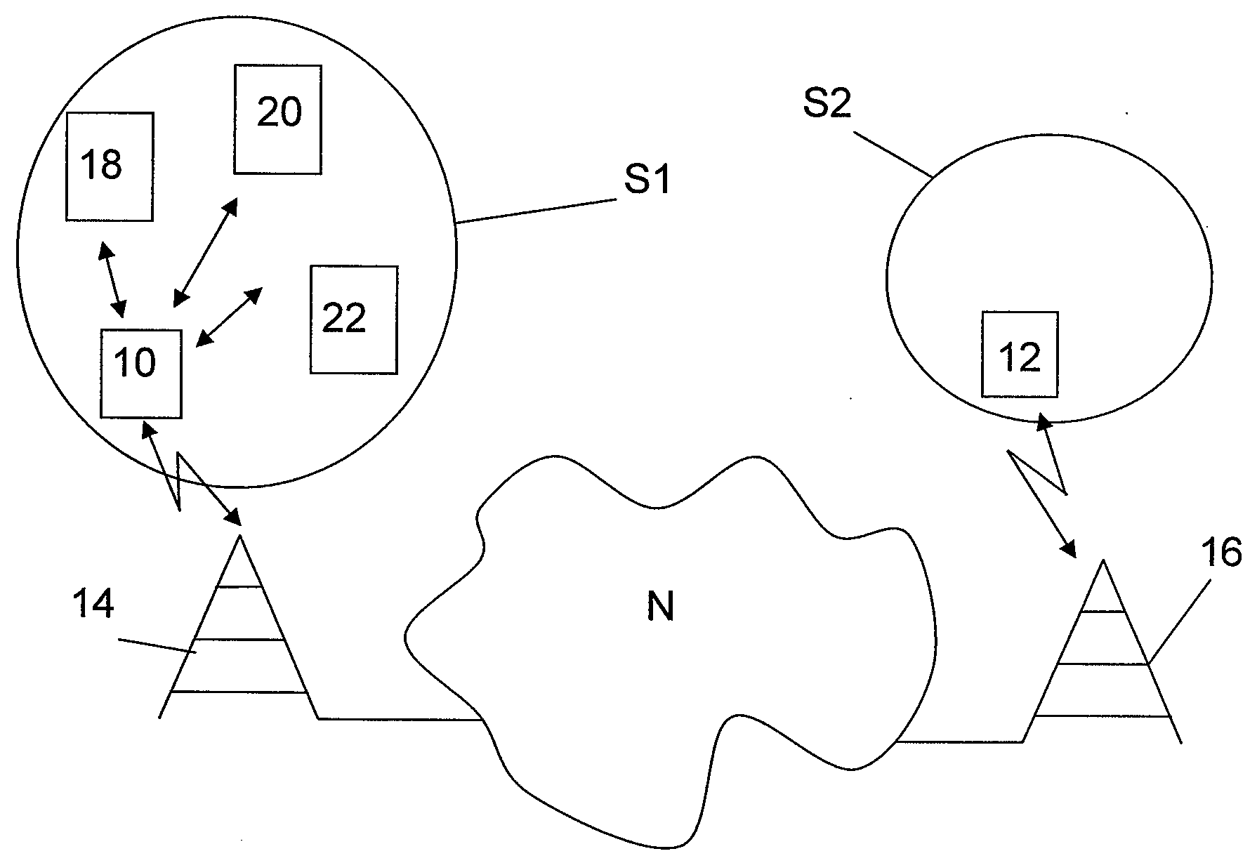
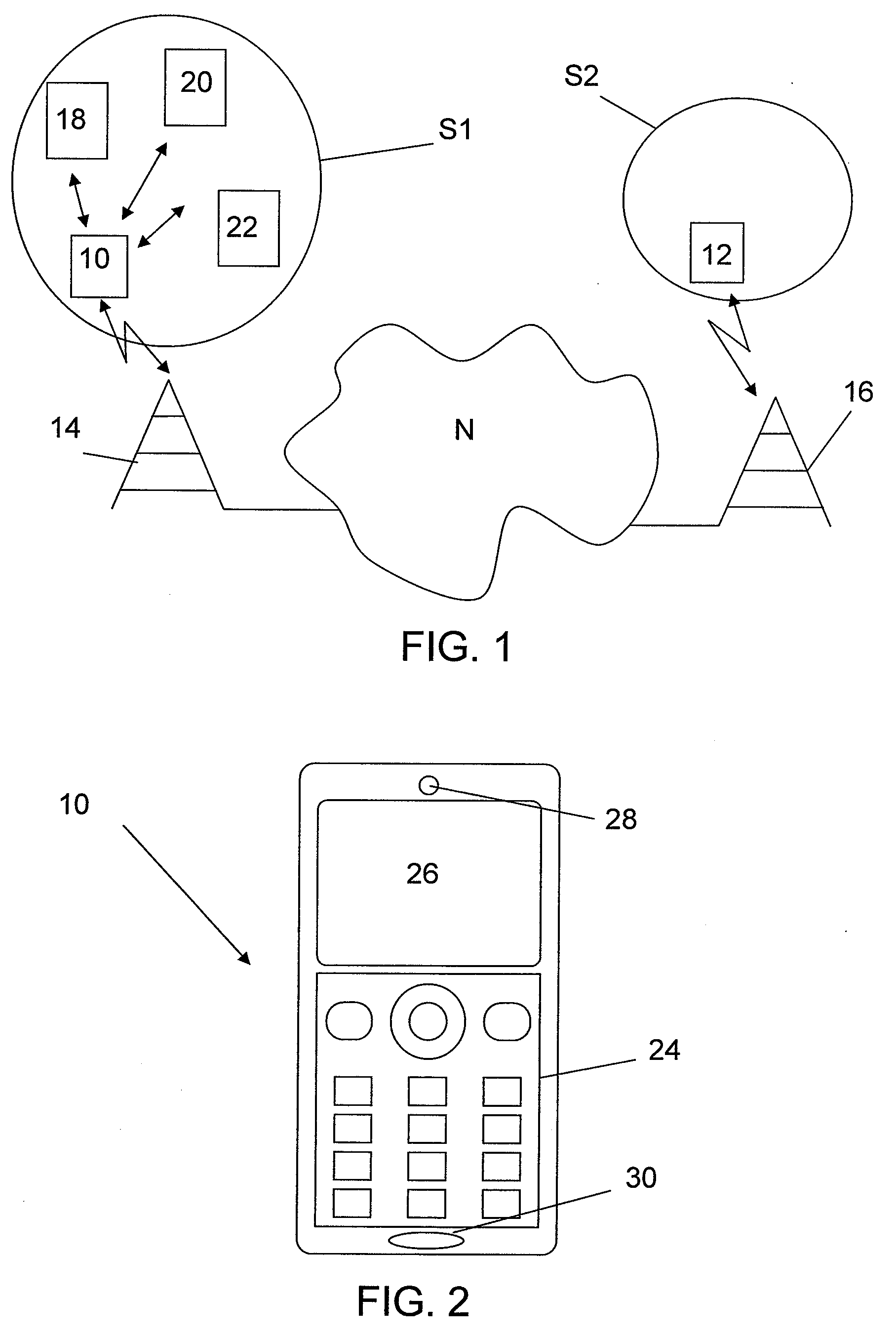
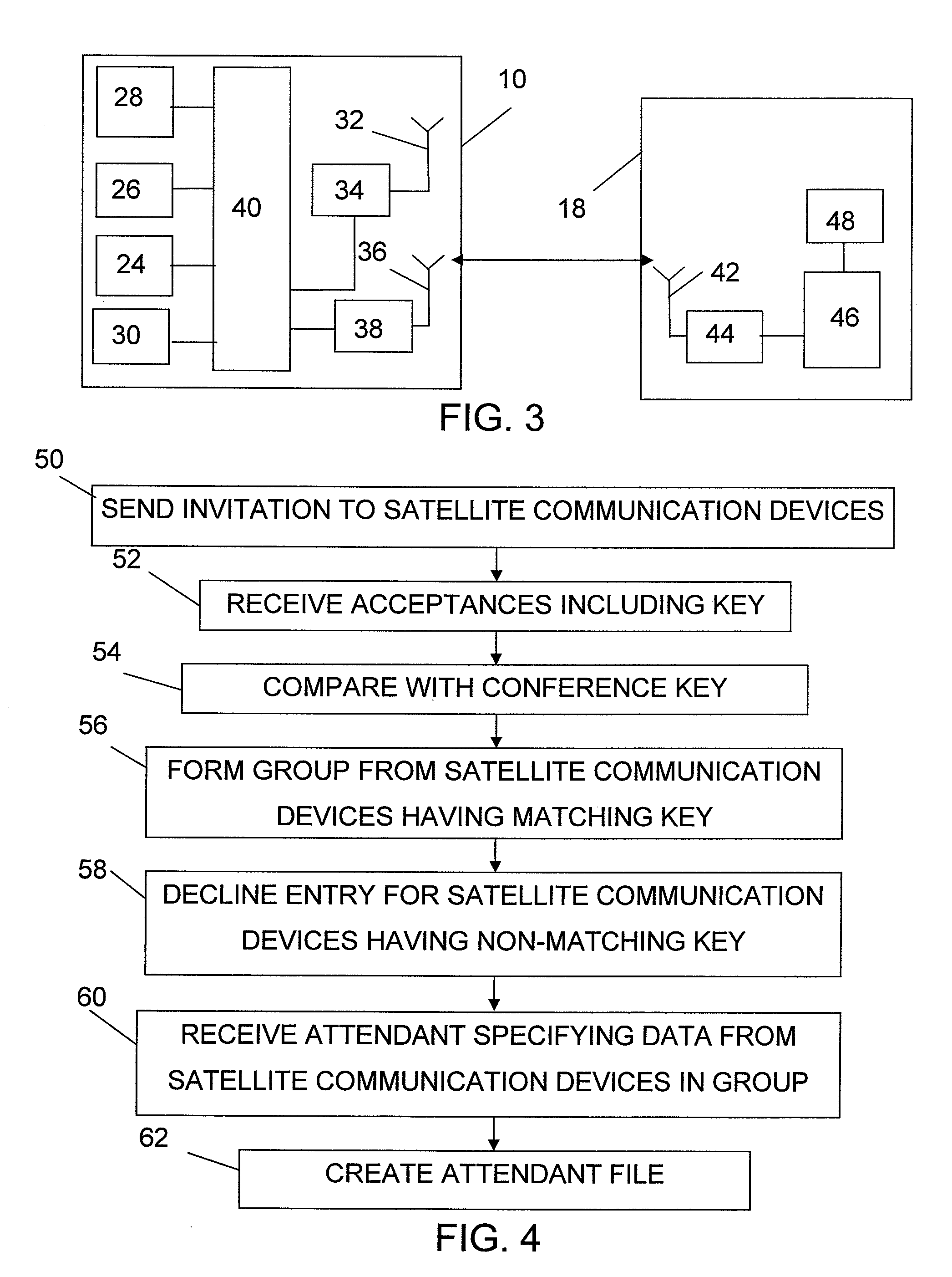
[0045]FIG. 1 schematically depicts a first main communication device 10 at a first site S1 communicating with a second main ...


PUM


Abstract

According to the present invention a first main communication device at a first site includes a first network interface associated with a communication network, a local wireless interface for interfacing with a number of satellite communication devices, a network communication unit for communicating over the first network interface, a local communication unit for communication with satellite communication devices via the local wireless interface, and a control unit. The control unit receives sound picked up by a group of satellite communication devices at the first site via the local wireless interface, combines this received sound, and orders the network communication unit to send the combined sound via the network interface to a second main communication device at a second site as sound in the conference communication session provided by the first main communication device.

Description

CROSS REFERENCE TO RELATED APPLICATION[0001]This application claims priority under 35 U.S.C. §119 based on U.S. provisional application No. 60 / 991,463, filed Nov. 30, 2007, the disclosure of which is hereby incorporated by reference herein in its entirety.TECHNICAL FIELD OF THE INVENTION[0002]The present invention relates generally to the field of conference communication sessions over communication networks and, more particularly, to a method, a communication device, and a computer program product for conference communication via a communication network between the communication device provided at a first site and at least one other communication device provided at a second site.DESCRIPTION OF RELATED ART[0003]Conference communication equipment, such as conference phones, typically includes a telephone equipped with one or more speakers and often having one or more microphones. When such conference equipment is to be put in use, the microphones may then be placed on a table at a fi...

Claims


Application Information

Patent Timeline
IPC IPC(8): H04M3/42
CPCH04M3/56H04M3/568H04M2250/62H04M2250/02H04M3/569
Inventor SASSI, JARI
Owner SONY ERICSSON MOBILE COMM AB
Learn More