Optimum code generation method and compiler device for multiprocessor

a multi-processor and compiler technology, applied in computing, instruments, electric digital data processing, etc., can solve the problems of slow processing of processors, long transfer time from main memory, and inability to achieve the proportional improvement of data supply performance of main memory proportional to the enhanced processing performance of processors

Active Publication Date: 2009-04-30
HITACHI LTD
View PDF20 Cites 32 Cited by
  • Summary
  • Abstract
  • Description
  • Claims
  • Application Information

AI Technical Summary

Benefits of technology

[0012]Further, in the method of generating optimum codes according to an embodiment of the present invention, it is also possible for its user to determine an optional range in the source codes in advance and designate whether the division of the first method or the division of the second method is applied thereto. By this means, while making the most of the user's knowledge and experience and the like, the optimization in accordance with the process contents can be achieved for each range in the source codes. As a result, it is possible to generate optimum parallel codes as a whole.

Problems solved by technology

However, the improvement in data supply performances from the main memory proportional to the enhanced processing performances of processors has not been achieved.
Accordingly, the problem occurs in which the data transfer time from the main memory becomes long and the processes in the processors are stopped during the time, and the performances of plural processors cannot be fully exerted.
However, the capacity of the cache memory that one processor can use for calculations is reduced to ¼. As a result, the problem occurs in which the capacity of the cache memory provided for one processor becomes small, and the amount of data to be reused is decreased.
Therefore, the local data access of the cache memory is lost, and the data reusability is deteriorated.

Method used


Image

  • Optimum code generation method and compiler device for multiprocessor
  • Optimum code generation method and compiler device for multiprocessor
  • Optimum code generation method and compiler device for multiprocessor

Examples


first embodiment

[0046](First Embodiment)

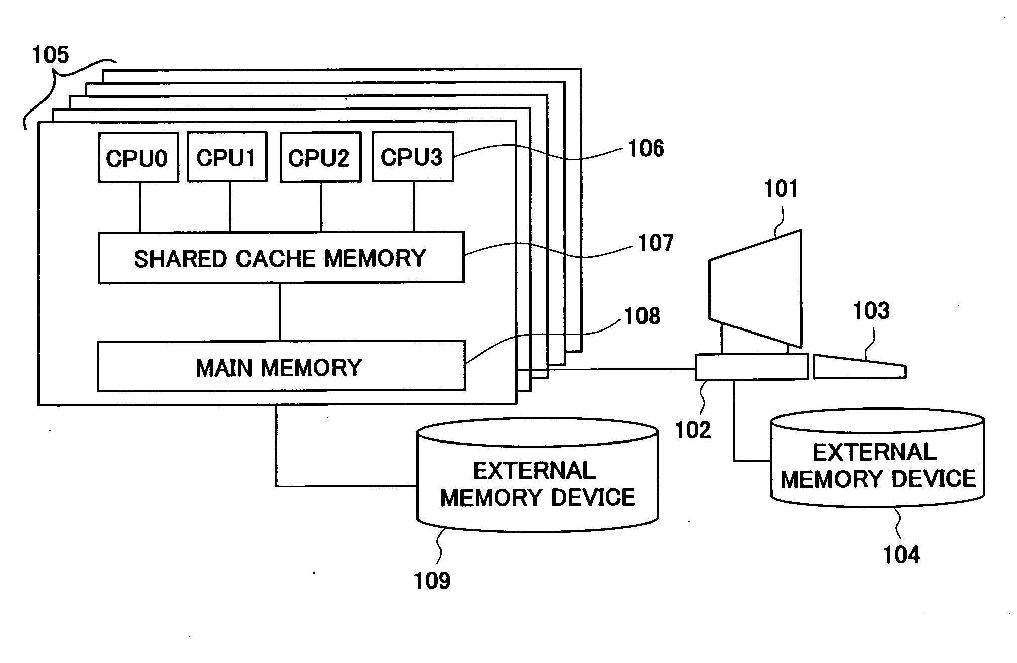
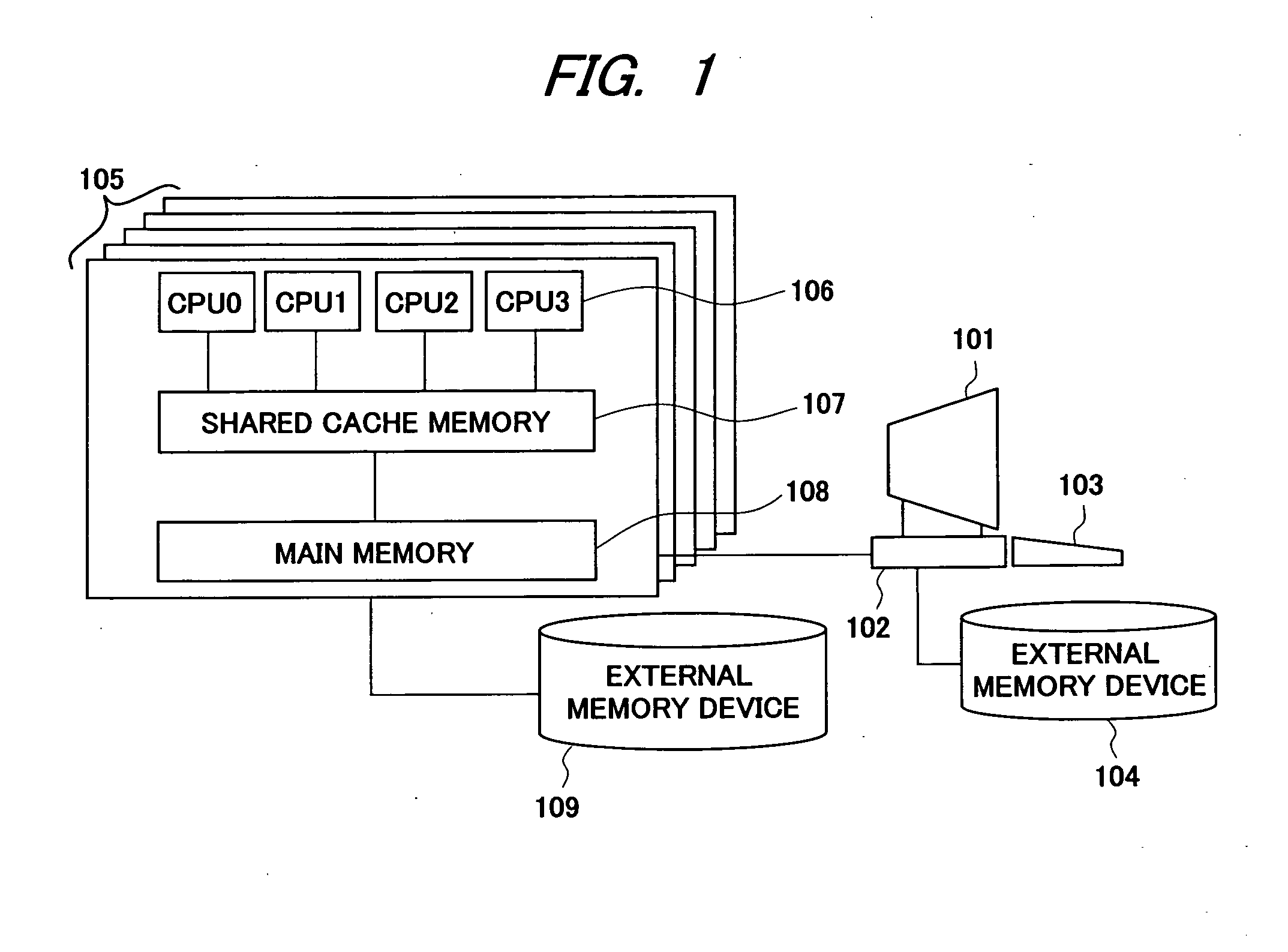
[0047]FIG. 1 is a configuration diagram showing an example of a computer system that executes the control by using the codes generated in a code generation method according to a first embodiment of the present invention. The computer system includes a display unit 101 and a terminal unit 102 for executing the codes, a keyboard 103 to input commands, an external memory device 104 connected to the terminal, a calculation node group 105 for executing the codes, and an external memory device 109 connected to the calculation node group.

[0048]One calculation node comprises plural processors (CPU) 106 that share a main memory device 108 or a cache memory 107, and the calculation node group is configured of one or plural calculation nodes. Commands are inputted from the keyboard 103 and the terminal unit 102, and generated codes are executed by the calculation node group 105. In the present embodiment, the generation method of parallel codes for efficiently operating...

second embodiment

[0107](Second Embodiment)

[0108]In a second embodiment, an example of the code generation method in the case where CPU does not comprise a shared cache in FIG. 1 in the first embodiment mentioned above will be described. FIG. 23 is a configuration diagram showing an example of a computer system that executes the control by using the codes generated in a code generation method according to the second embodiment of the present invention. The computer system in FIG. 23 has a configuration in which the shared cache is removed from the computer system in FIG. 1, and a shared memory 2307 is connected to each processor (CPU) 2306 in a calculation node group 2305.

[0109]Even in the case where no shared cache is disposed among plural processors as shown above, there are two types of parallelization methods similar to the first embodiment. For example, in the case where “calculation” is selected in 606 in FIG. 6, the operation load equalization parallelization method to divide the loop control ...

third embodiment

[0115](Third Embodiment)

[0116]In a third embodiment, an example of the code generation method in the case where the loop control variable of the source code 701 in FIG. 7 in the first embodiment mentioned above is given by a variable instead of a constant will be described. FIG. 26 is a diagram showing an example of a source code to be an evaluation objective in the code generation method in the third embodiment of the present invention. In the source code 2601 shown in FIG. 26, the loop control variable i=1 to 400 that is a constant in the source code 701 in FIG. 7 is given by a variable i=m to n.

[0117]In such a case, in the analysis procedure of dependent process and independent process and the analysis procedure of data reusability in FIG. 12 and the analysis procedures of reusability of the used data in FIG. 16, the data amount is analyzed with using the variable directly. In the example of the reuse data table in FIG. 14 and the example of the main memory data table in FIG. 15,...


PUM


Abstract

A method of generating optimum parallel codes from a source code for a computer system configured of plural processors that share a cache memory or a main memory is provided. A preset code is read and operation amounts and process contents are analyzed while distinguishing dependence and independence among processes from the code. Then, the amount of data to be reused among processes is analyzed, and the amount of data that accesses the main memory is analyzed. Further, upon the reception of a parallel code generation policy inputted by a user, the processes of the code are divided, and while estimating an execution cycle from the operation amount and process contents thereof, the cache use of the reuse data, and the main memory access data amount, a parallelization method with which the execution cycle becomes shortest is executed.

Description

CROSS-REFERENCE TO RELATED APPLICATION[0001]The present application claims priority from Japanese Patent Application No. JP2007-275886 filed on Oct. 24, 2007, the content of which is hereby incorporated by reference into this application.TECHNICAL FIELD OF THE INVENTION[0002]The present invention relates to an optimum code generation method and a compiler device for a multiprocessor. More particularly, it relates to a method of generating codes for parallel processing and a compiler device for efficiently operating a plurality of processors.BACKGROUND OF THE INVENTION[0003]Along with the development of semiconductor manufacturing technologies, the high integration of transistors has been realized and processors have achieved high computing power. On the other hand, there has been a problem of large power consumption due to high operating frequencies and leakage current of the processors. As a method to avoid this problem, as described in C. Scott Ananian, Krste Asanovic, Bradley C. ...

Claims


Application Information

Patent Timeline
Patent Type & Authority Applications(United States)
IPC IPC(8): G06F9/45
CPCG06F8/452
Inventor TAKAYAMA, KOICHISUKEGAWA, NAONOBU
Owner HITACHI LTD
Why Eureka
Try Eureka