
Zero Hysteresis Electric Ratchet Socket Driver

a technology of electric ratchets and socket drivers, applied in the field of hand tools, can solve the problems of large motors that require larger, and heavier, insufficient torque delivered by pneumatic ratchets, and large hand tools

Inactive Publication Date: 2009-05-07
LAWRENCE CARL EUGENE
View PDF8 Cites 14 Cited by
  • Summary
  • Abstract
  • Description
  • Claims
  • Application Information

AI Technical Summary

Benefits of technology

[0020]Accordingly, it is an objective of the invention to provide a ratcheting tool having a drive means to automatically turn fasteners quickly at low torque loads.

Problems solved by technology

The challenge in designing most of the prior art tools is to produce enough torque at the output shaft.
For battery powered versions of these tools, the larger motors require larger, and heavier, batteries.
The large motors and large batteries required generally lead to a very large, heavy hand tool.
Only when the fastener is very tight is the torque delivered by the pneumatic ratchet insufficient to move the fastener.
With such a limitation of physical size the power of the motor will, in accordance, be limited.
When the fastener is snug or tight the motor will slow.
When conventional ratchets are used in this situation there is quite often insufficient resistive torque of the fastener to operate the mechanical ratcheting mechanism.
The conventional ratcheting means does not have enough resistive torque to operate.
When a conventional ratchet is used there may not be enough room to swing the lever arm back to the point where the next catch of the ratcheting means is achieved.
As the lever arm of the conventional ratchet is moved back and forth at a small angle caused by the limited space, there is insufficient room for the ratcheting means to operate do to the mechanical ratchet's inherent hysteresis.

Method used


Image

  • Zero Hysteresis Electric Ratchet Socket Driver
  • Zero Hysteresis Electric Ratchet Socket Driver

Examples


Embodiment Construction

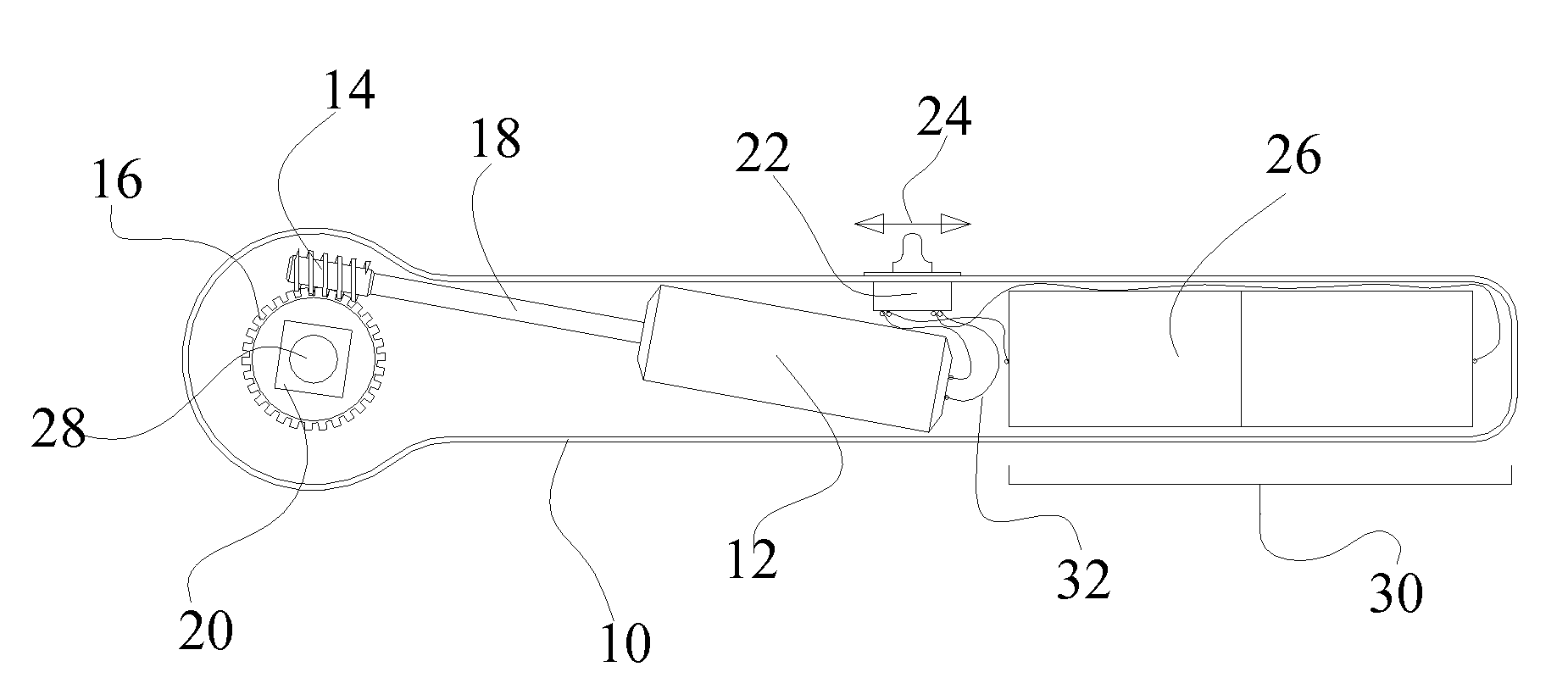
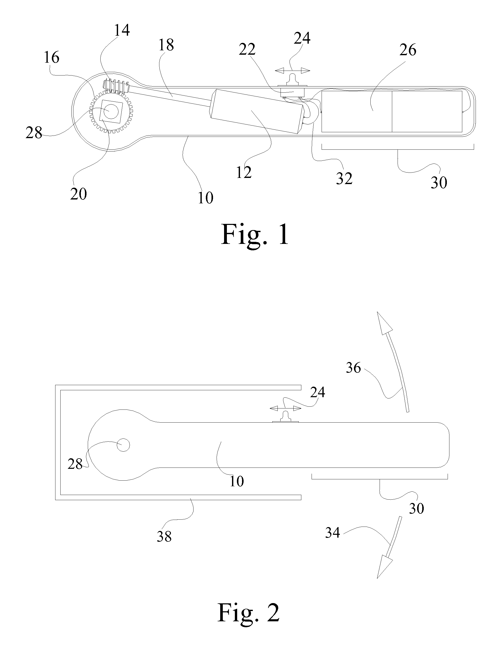
[0040]FIG. 1 and FIG. 2 illustrate a possible embodiment of the invention. Many other embodiments of the invention can be anticipated when based on the claims of this invention.

[0041]The invention has the conventional topography of a mechanical ratcheting tool used to drive a socket for the tightening and loosening of threaded fasteners, such as nuts and bolts. As shown in FIG. 1 the body 10 of the invention is used to enclose the components of the invention and to provide a means for applying a force to the invention. Within the body 10 is a battery 26, switch 22, motor 12, motor shaft 18, pion gear 16, worm gear 14, and the wires 32. The battery 26 is rechargeable and electrically connected to the motor 12 through a switch 22 via a set of wires 32. The motor 12 is connected to the worm gear 14 through a shaft 18. The worm gear 14 is in mesh with the pion gear 16. The pion gear 16 is connected to square output shaft 20, and onto the square output shaft 20 is where the sockets are i...


PUM


Abstract

The invention is an improved ratchet to drive sockets for the purpose of tightening or loosening threaded fastener. The invention contains an electric motor, battery and worm gear system to drive the sockets. The battery and motor are contained within the handle of the invention and are thus limited in size and power. A switch is also located on the handle and is used to activate the motor in the desired direction. The motor is powerful enough to drive most fasteners when the fasteners are somewhat loose, and as such the invention can drive the loose fasteners rapidly. At such times when the fasteners are snug or tight the invention will perform as a conventional ratchet. As the handle is pulled the worm and pion gears will lock and transmit the torque to the socket. As the handle is released the motor will drive the worm and spin the pion gear / socket and take up all of the slack. The invention operates as a zero hysteresis ratcheting socket driver when the fastener is snug and as an electrically powered ratchet when the fastener is loose. The invention is of superior advantage when used in confined spaces with limited access to the socket end and limited room to swing the handle end.

Description

CROSS-REFERENCE TO RELATED APPLICATIONS[0001]60 / 866,435FEDERALLY SPONSORED RESEARCH[0002]NoneSEQUENCE LISTING[0003]NoneBACKGROUND[0004]1. Field of Invention[0005]This invention relates to hand tools used to apply torque to threaded fasteners, such as nuts and bolts, and more specifically to such tools that use a ratcheting means having an electric motor and a battery.[0006]2. Description of Prior Art[0007]The prior art consists of many electrically and pneumatically driven hand tools such as wrenches, screw drivers, drills and ratchets. Some such tools are battery powered and some are powered by AC line voltage. In known cases there is either an electric motor or a force pulsing means used to produce the torque to drive the sockets fitted to the bolts and nuts. Most commonly, the electric motor drives through spur gears to reduce the motor speed to a predetermined fastener driving speed.[0008]The challenge in designing most of the prior art tools is to produce enough torque at the o...

Claims


Application Information

Patent Timeline
IPC IPC(8): B25B23/157B25B21/00B25B13/46
CPCB25B21/004B25B21/00
Inventor LAWRENCE, CARL EUGENE
Owner LAWRENCE CARL EUGENE
Learn More