Stationary band clamping apparatus

a clamping apparatus and stationary technology, applied in the field of clamping tools, can solve the problems of reducing the chance of thinning and severing the band prematurely, affecting the operation of the clamping apparatus, and the edge may have a tendency to puncture or cut the band, so as to facilitate the access of bulky or cumbersome work pieces and enhance the effect of operation repeatability

Active Publication Date: 2009-05-07
BAND IT IDEX
View PDF99 Cites 70 Cited by
  • Summary
  • Abstract
  • Description
  • Claims
  • Application Information

AI Technical Summary

Benefits of technology

[0007]It is one aspect of the present invention to provide an adjustably mounted clamping tool or device. More specifically, embodiments of the present invention are interconnected to a stationary slide that allows movement of the tool relative to a fixed base. Further, the clamping device is also capable of pivoting with respect to the base. This functionality allows the operator to more easily access bulky or cumbersome work pieces. For example, with the work piece secured in a vise or otherwise stabilized, the...

Problems solved by technology

However, the teeth or edges may have a tendency to puncture or cut the band as it is tensioned, particularly if the teeth or edges of the teeth extend continuously or near continuously across the entire width of the band, which essentially creates a knife edge across the width o...

Method used


Image

  • Stationary band clamping apparatus
  • Stationary band clamping apparatus
  • Stationary band clamping apparatus

Examples


Embodiment Construction

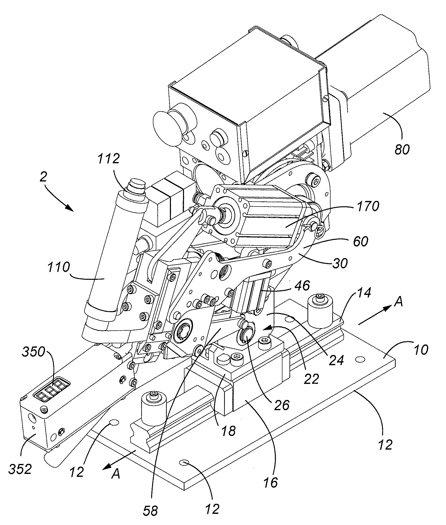
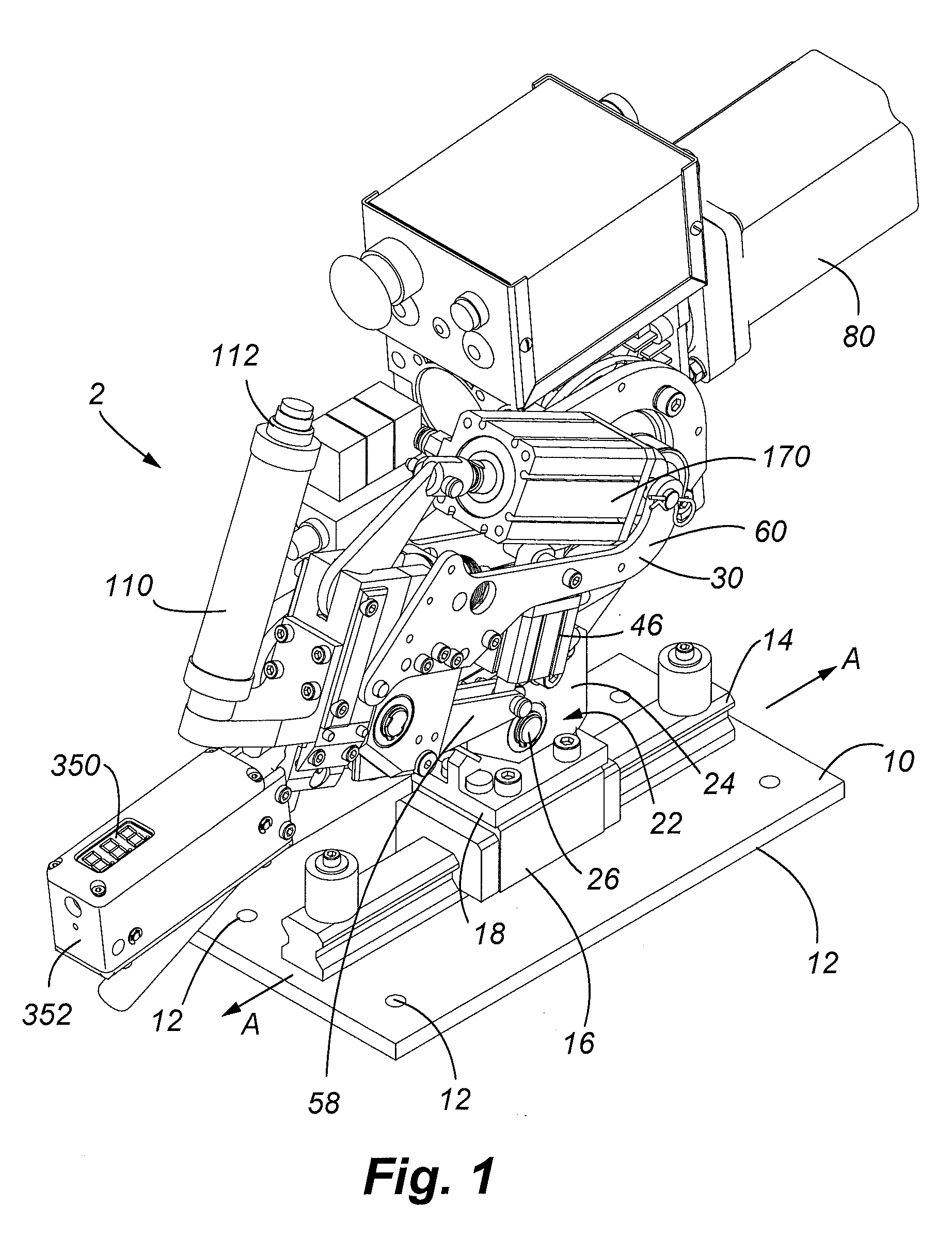
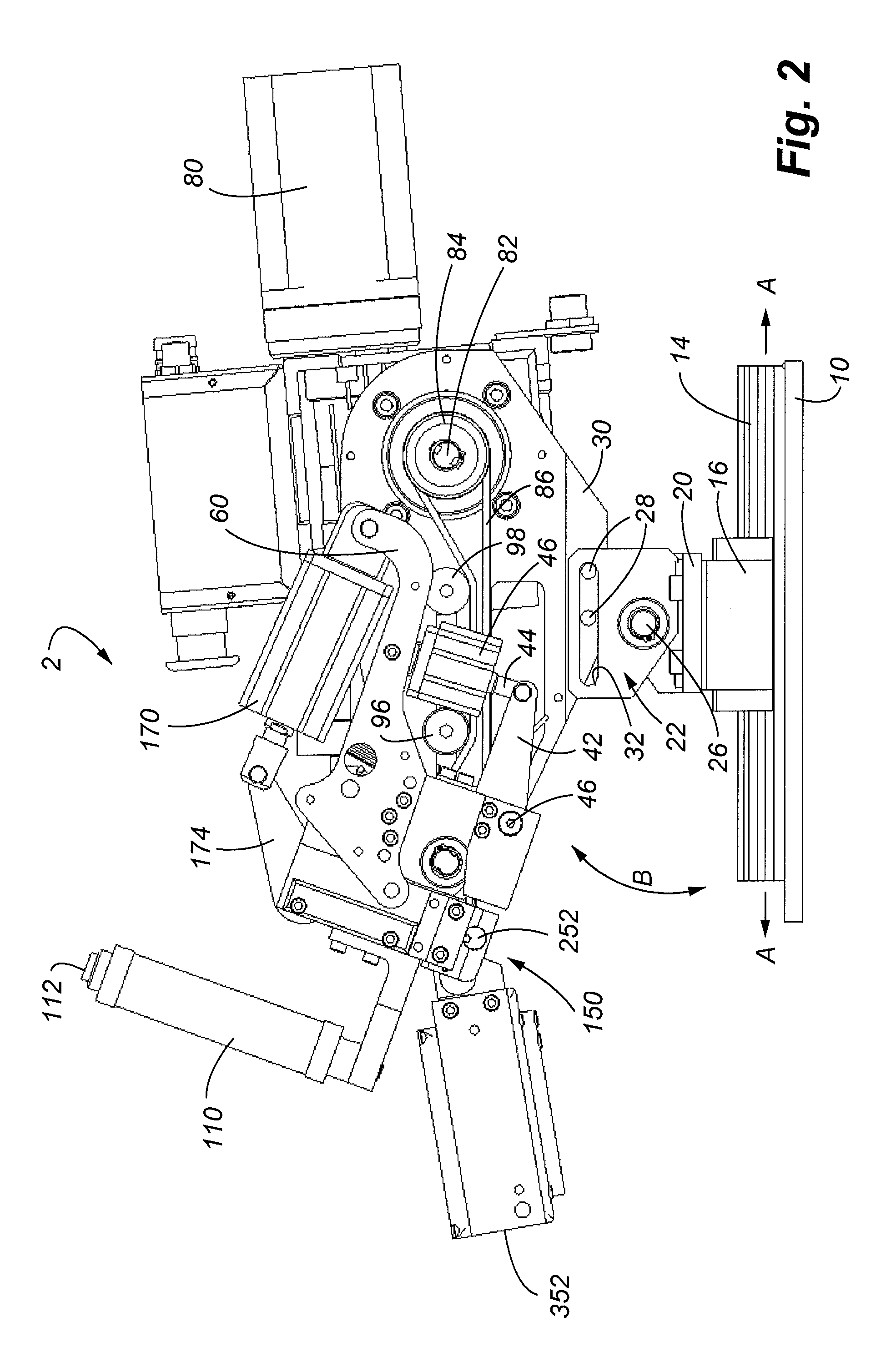
[0048]Referring now to FIGS. 1-3, the tensioning device 2 of one embodiment of the invention is shown. The tension device or tool 2 includes a base 10 that is mountable to another structure via securement holes 12. A track or slide rail 14 is secured to the base 10. A slide mount 16 is slidably interconnected on the slide rail 14 and allows the tensioning device 2 to be moved relative to base 10 in the direction of arrow A (FIGS. 1 and 2). A mounting block 18 is secured to the slide mount 16. The mounting block 18 includes an upstanding plate 20 with an aperture (not shown) located generally in the center of the plate 20. A mounting bracket 22, formed by a pair of parallel spaced apart plates 24 straddle opposite sides of plate 20. Plates 24 include apertures such that a pivot or bearing 26 may be used to interconnect the three plates 22 and 24 to permit the device 2 to rotate or pivot relative to the fixed base 10 in the direction of arrow B (FIGS. 2 and 3). The mounting bracket 22...


PUM

PropertyMeasurementUnit
Lengthaaaaaaaaaa
Thicknessaaaaaaaaaa
Forceaaaaaaaaaa

Abstract

A tensioning device is provided that includes a separable punching and cutting mechanism. Provided is an impact head that holds a buckle while the band that resides within the buckle is tensioned. After a predetermined tension is achieved, a mechanism is used to lock the band with respect to the buckle then to cut the band. Various data related to tension and cutting performance may also be outputted by the invention.

Description

CROSS-REFERENCE TO RELATED APPLICATIONS[0001]This patent application claims the benefit of pending U.S. Provisional Patent Application Ser. No. 61 / 035,999, filed Mar. 12, 2008 entitled “Stationary Band Clamping Apparatus,” the entire disclosure of which is incorporated by reference herein. This patent application also claims the benefit of pending U.S. Provisional Patent Application Ser. No. 60 / 985,142, filed Nov. 2, 2007 entitled “Dual Locking General Purpose Clip and Method of Forming the Same,” the entire disclosure of which is incorporated by reference herein.[0002]This patent application is related to U.S. Pat. No. 5,123,456 issued Jun. 23, 1992, entitled “Banding Tool Including Clamping Plunger” and U.S. Pat. No. 6,481,467 issued Nov. 19, 2002, entitled “Powered Band Clamping Under Electrical Control,” both being incorporated by reference in their entirety herein.FIELD OF THE INVENTION[0003]Embodiments of the present invention are related generally to banding tools, and in par...

Claims


Application Information

Patent Timeline
IPC IPC(8): B21F9/02
CPCB65B13/02B65B13/025B65B13/345B65B13/188B65B13/22B65B13/185B65B13/24B65B61/04
Inventor MARELIN, MIKLOS BALAZSLEIST, RENEDORNEMAN, CASEY JAMESNELSON, DANIEL J.
Owner BAND IT IDEX
Why Eureka
Try Eureka