Drum brake shoe

a technology of drum brakes and shoes, applied in the field of drum brake shoes, can solve the problems of difficult movement, difficult removal, and complicated movement that has to be performed

Active Publication Date: 2009-05-07
CHASSIS BRAKES INT BV
View PDF4 Cites 1 Cited by
  • Summary
  • Abstract
  • Description
  • Claims
  • Application Information

AI Technical Summary

Benefits of technology

[0009]One essential advantage of the drum brake according to the invention is the ease with which the brake cable can be re

Problems solved by technology

This removal is tricky to perform because the lever is located behind one of the shoes and the movement that has to b

Method used


Image

  • Drum brake shoe
  • Drum brake shoe
  • Drum brake shoe

Examples


Embodiment Construction

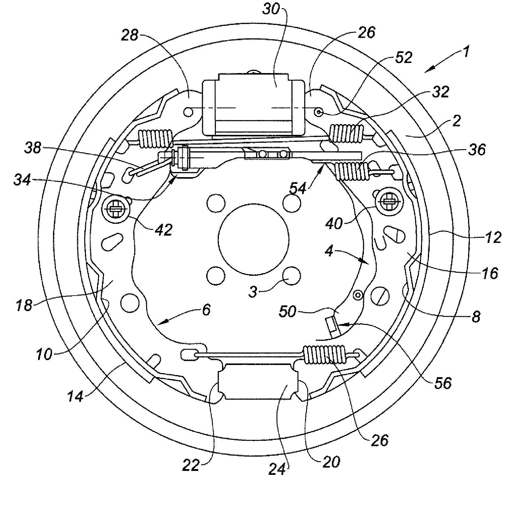
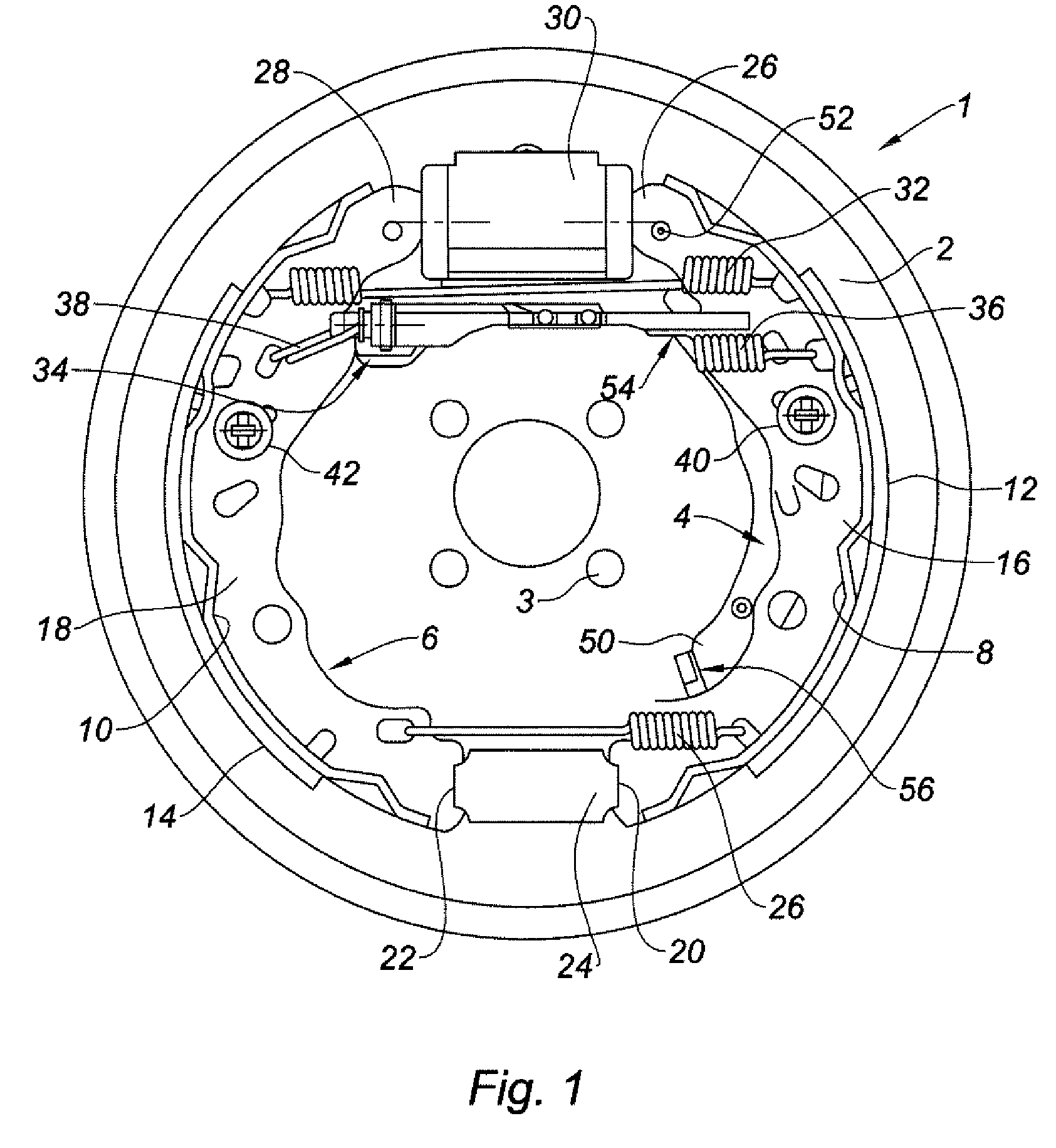
[0023]FIG. 1 depicts a drum brake device 1 which, in a known way, comprises a supporting backplate 2 in the form of a disk fixed to the chassis of a vehicle by screws that pass through drillings 3 positioned around a central opening through which there fits the hub of a wheel which turns a brake drum, not depicted.

[0024]The backplate 2 supports two shoes 4, 6 each comprising a part 8, 10 of cylindrical surface coaxial with the drum and onto which a friction lining 12, 14 is bonded. Each shoe comprises a rigid web 16, 18 made of sheet metal running in a plane perpendicular to the axis of the drum and connected to the cylindrical part 8, 10.

[0025]Each shoe 4, 6 can pivot about a lower end 20, 22 resting against a stop 24 connected to the backplate 2, under the effect of a main hydraulic control comprising a horizontal cylinder 30 fixed to the backplate 2 and accommodating two pistons positioned axially on each side of a fluid-tight chamber that receives pressurized oil from a supply p...


PUM


Abstract

Drum brake shoe, particularly for a motor vehicle, in which a brake cable (64) has an end terminal (66) for attachment to a lever (50) that acts on the shoe (4), this shoe comprising a rigid web one edge of which is formed with a cut-out (90) providing access to the cable (64) attachment end terminal (66) to make it easier to detach this cable.

Description

BACKGROUND AND SUMMARY OF THE INVENTION[0001]The present invention relates to a drum brake shoe, particularly for a motor vehicle, and to a drum brake equipped with this shoe.[0002]A drum brake in general comprises a fixed backplate which is perpendicular to the axis of a drum that rotates as one with a wheel, and which supports shoes fitted with arc-shaped friction linings. A cylinder-actuated main control is able to push these shoes radially outward and press the linings against the cylindrical interior face of the drum that rotates as one with the wheel, in order to brake this wheel.[0003]To create a parking or hand brake, an additional control is provided, this comprising a cable pulled by a lever actuated by the driver. The cable slides in a sheath the end of which bears against the backplate, the end of the cable acts on a lever which pivots and multiples the force to expand (part) the shoes and apply the linings firmly against the drum.[0004]A drum brake of this type, describ...

Claims


Application Information

Patent Timeline
IPC IPC(8): F16D51/04F16D65/22
CPCF16D51/00Y10T74/20402F16D2125/62
Inventor DUPAS, CHRISTOPHEPEREZ, MIGUELCORNIC, MATTHIEU
Owner CHASSIS BRAKES INT BV
Why Eureka
Try Eureka