Rotor For An Electrical Machine

a rotor and electrical machine technology, applied in the direction of dynamo-electric machines, magnetic circuit rotating parts, magnetic circuit shape/form/construction, etc., can solve the problems of non-uniform angular speed of the rotor, detent torque, cogging torque, etc., and achieve the effect of easy assembly

Inactive Publication Date: 2009-05-07
SPAL AUTOMOTIVE
View PDF20 Cites 37 Cited by
  • Summary
  • Abstract
  • Description
  • Claims
  • Application Information

AI Technical Summary

Benefits of technology

[0013]In this context, the main purpose of the present invention is to propose an embedded magnet rotor which is easy to assemble and in which the position of the magnets when the rotor is at rest does not change when the motor is switched on and the rotor starts turning.
[0014]Another aim of the invention is to provide a rotor with a balanced weight distribution under both static and rotating conditions.
[0015]Yet another aim of the invention is to provide a rotor, especially for brushless motors, that reduces cogging torque during motor operation.

Problems solved by technology

One disadvantage of motors that use rotors of this kind is due to the magnetic attraction between the magnets in the rotor and the poles on the stator giving rise to what is commonly referred to as “cogging torque” or “detent torque”
Cogging torque causes non-uniformity in the angular speed of the rotor, which tends to rotate in a series of small “jerky” movements instead of smoothly and continuously.
Embedded magnet rotors are also difficult to balance and assemble, especially when the magnets are inserted into the longitudinal slots.
The result is that in prior art rotors, however small these dimensional differences between slots and magnets may be, the magnets are not held firmly in place and the centrifugal force created by the rotational motion pushes them against the radially outermost wall of the slot.
In other words, the position of the magnets relative to the rotor core changes when the motor is started, making it very difficult to optimise flows and geometry in the motor design.
Optimisation of geometry is also made more difficult by concentricity errors in the different sheets making up the rotor due to the fact that the sheets are cut at different times. These errors cause rotor unbalance.

Method used


Image

  • Rotor For An Electrical Machine
  • Rotor For An Electrical Machine
  • Rotor For An Electrical Machine

Examples


Embodiment Construction

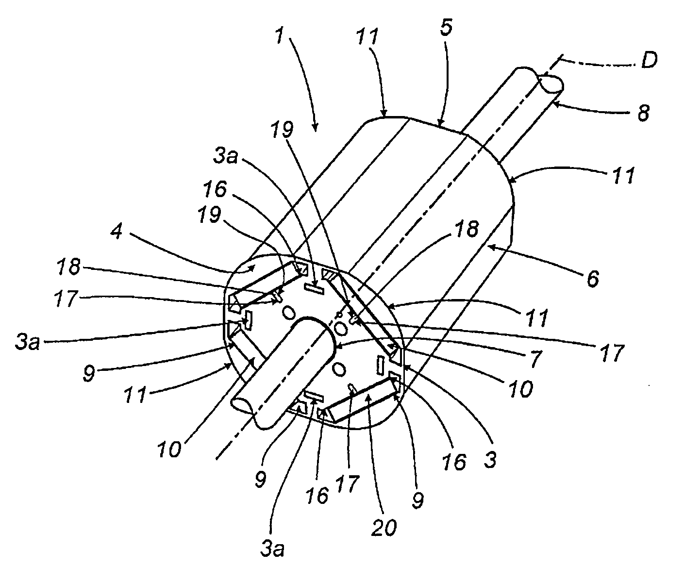
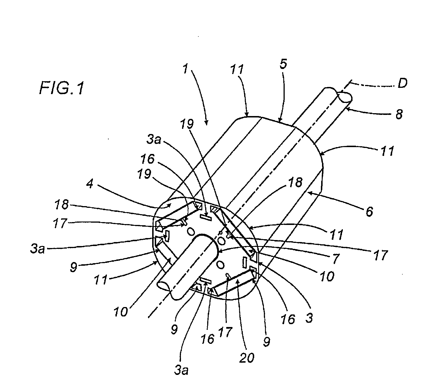
[0030]With reference to the accompanying drawings, the numeral 1 denotes a rotor, according to the present invention, for an electric motor M.

[0031]As shown in FIGS. 4 and 6, the motor M comprises a stator 200 which accommodates the rotor 1.

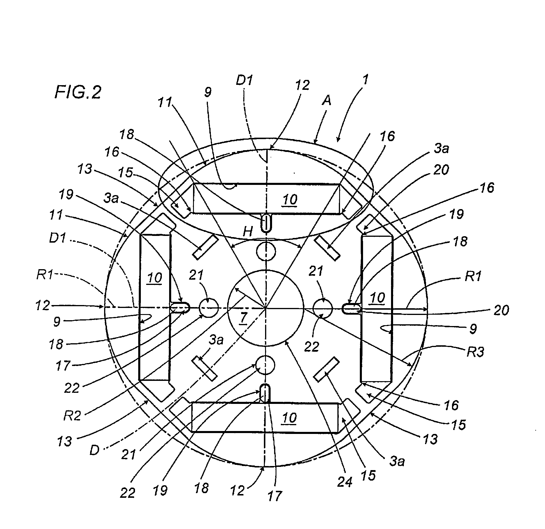
[0032]The rotor 1 has a principal axis of rotation D, normally coinciding with the axis of the motor M, and comprises a laminated core 2, that is to say, consisting of a plurality of thin laminations 3 firmly joined to each other by bonding elements 3a (assembled according to what is known as “stacking technology”) delimited by a first and a second end wall 4, 5 and by a lateral surface 6.

[0033]The core 2 has a longitudinal hole 7, whose axis substantially coincides with the principal axis D, for coupling with a motor shaft 8.

[0034]The first and second end walls 4, 5 are preferably parallel with each other. To guarantee this parallelism, the laminations 3 are grouped together in stacks which are bonded to form the laminated core 2.

[0035]Advantage...


PUM


Abstract

A rotor (1) for an electric motor with permanent magnets (10) has a principal axis (D), comprises a laminated core (2) delimited by a first and a second end wall (4, 5) and by a lateral surface (6) and has a hole (7) for coupling to a motor shaft (8) and a plurality of longitudinal slots (9) for housing the magnets (10); the rotor also comprises positioning devices (20) for stabilizing the magnets (10) in the slots (9).

Description

TECHNICAL FIELD[0001]This invention relates to a rotor for an electrical machine and, in particular, a rotor having permanent embedded magnets, that is, magnets that are seated in slots made in the rotor itself.BACKGROUND ART[0002]Embedded magnet rotors of known type, used especially in brushless motors, usually consist of a laminated core, that is to say, a core made up of a plurality of thin metal laminations and having a principal axis that coincides with the axis of rotation of the motor.[0003]The rotor normally has a plurality of longitudinal slots, parallel to the principal axis, and a central hole or opening, also parallel to the principal axis, for accommodating the magnets and a drive shaft, respectively.[0004]The rotor is mounted in a stator equipped with magnetic poles which, when powered, generate a magnetic field that interacts with the magnets and causes the rotor to turn.[0005]One disadvantage of motors that use rotors of this kind is due to the magnetic attraction be...

Claims


Application Information

Patent Timeline
Patent Type & Authority Applications(United States)
IPC IPC(8): H02K1/28
CPCH02K1/276H02K2201/06H02K29/03H02K1/27H02K1/22
Inventor SPAGGIARI, ALESSANDRO
Owner SPAL AUTOMOTIVE
Why Eureka
Try Eureka