Resonator Capable of Varying Its Resonance Frequency and Method for Varying Its Resonance Frequency

a technology of resonance circuit and frequency, which is applied in the direction of generator/motor, device details, magnetic bodies, etc., can solve the problems of deteriorating frequency tuning performance of the resonance circuit, affecting the and fundamentally difficult to achieve automatic selection of the desired frequency

Inactive Publication Date: 2009-05-07
MICROPRECISION
View PDF3 Cites 7 Cited by
  • Summary
  • Abstract
  • Description
  • Claims
  • Application Information

AI Technical Summary

Problems solved by technology

In order to change a capacitance of a variable capacitor, however, a mechanical force must be applied to the variable capacitor, so that it is fundamentally difficult to attain an automatic selection of a desired frequency.
When the Q value falls, a frequency tuning performance of the resonance circuit is deteriorated.

Method used


Image

  • Resonator Capable of Varying Its Resonance Frequency and Method for Varying Its Resonance Frequency
  • Resonator Capable of Varying Its Resonance Frequency and Method for Varying Its Resonance Frequency
  • Resonator Capable of Varying Its Resonance Frequency and Method for Varying Its Resonance Frequency

Examples


embodiment

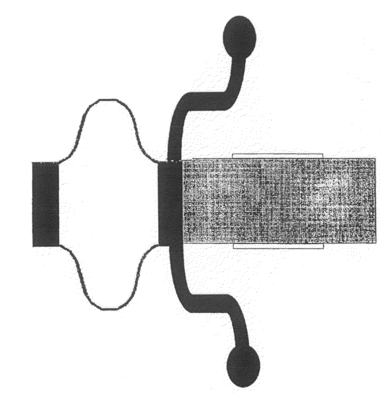
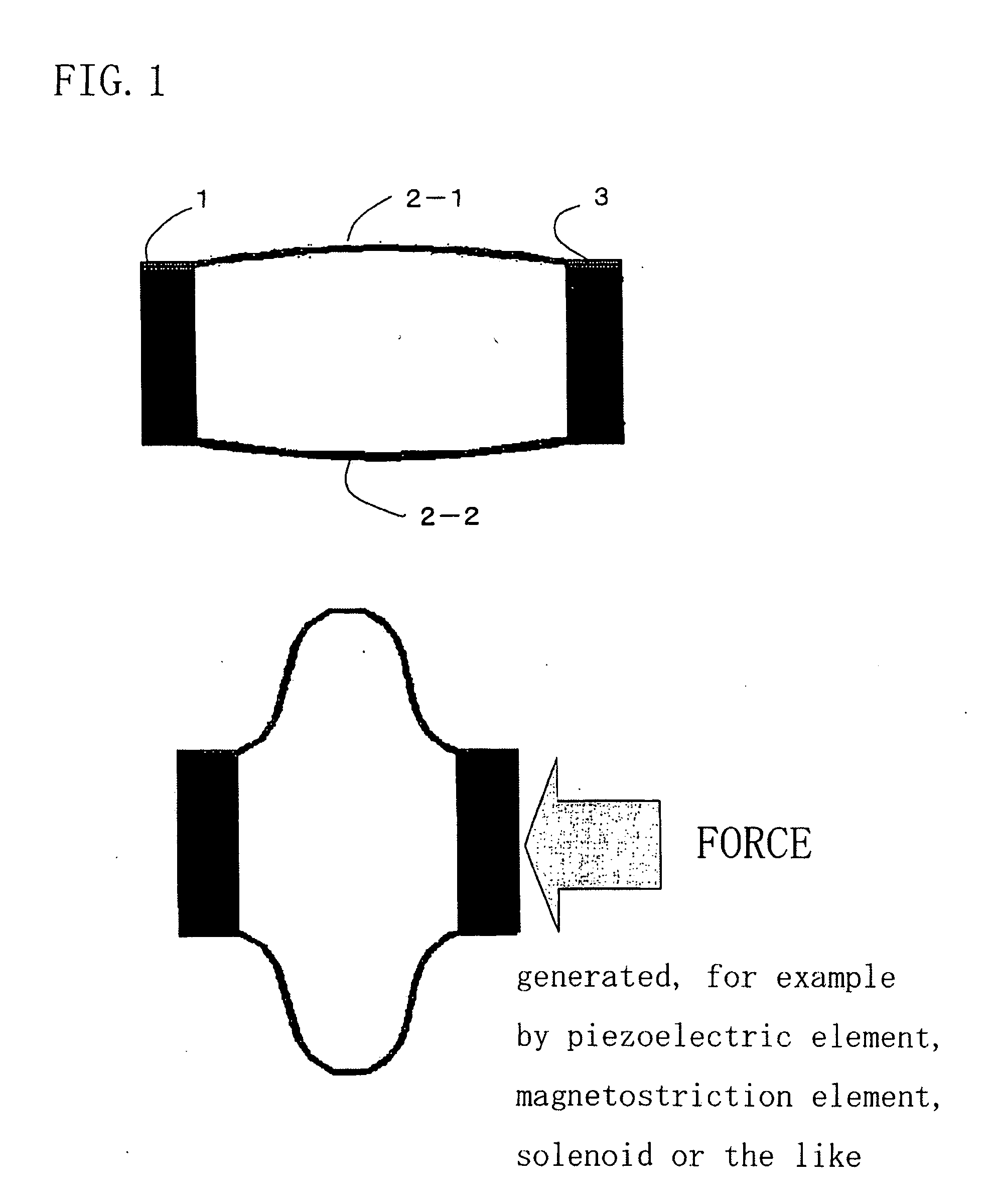
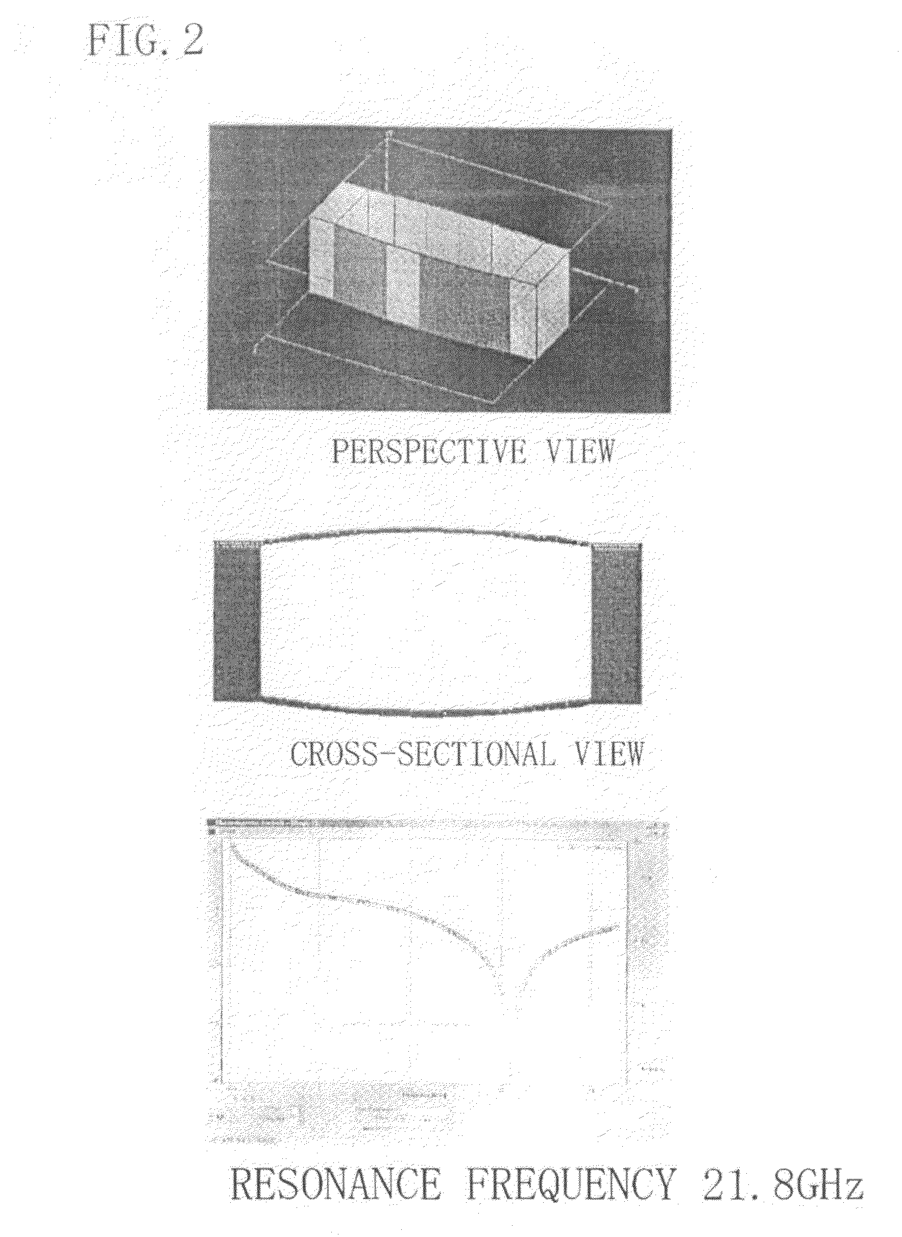
[0024]FIG. 1 is the schematic cross-sectional views for explaining the operational mechanism of the embodied “resonator capable of varying its resonance frequency” by the present invention. The resonator capable of varying its resonance frequency (hereinafter referred as merely “the element”) is constituted by a fixed electrode 1, a movable electrode 3 arranged with a predetermined distance apart from parallel to the fixed electrode, a pair of conductive leaf springs 2-1, 2-2 which are slightly bent outward beforehand and arranged parallel apart from each other. The fixed electrode 1 is fixed with the aid of an unshown component and external force is applied to the external electrode 3 in order to deform the element. A current path of the element has a capacitance determined by a distributed constant and an inductance, which are being varied in accordance with a deformed degree of the element, so that the resonance frequency of the element is being varied. A chart in FIG. 2 shows th...


PUM


Abstract

The present invention provides a resonator capable of varying its resonance frequency of good performance with a low dispersion at a high manufacturing yield and a low cost. The resonator comprises a fixed electrode 1; a movable electrode 3 arranged with a predetermined distance apart from and parallel to the fixed electrode; a plurality of conductive leaf springs 2 with conductive property, all of which are bent outward or inward beforehand, arranged parallel apart from each other wherein, one end of each leaf spring is integrated into the fixed electrode and the other end of each leaf spring is integrated into the movable electrode; and an actuator 6 attached to the movable electrode for deforming the leaf springs by pushing or pulling the movable electrode.

Description

FIELD OF THE INVENTION[0001]The present invention relates to an electrical resonator capable of varying of its resonance frequency, particularly relates to lowering its manufacturing cost.RELATED BACKGROUND ART[0002]Variable capacitors, which have been used for a long time, are employed in broadcasting radio receivers, television receivers and the like together with inductors. The combined variable capacitors are useful for selecting tuning (or resonance) frequencies in such receivers. In order to change a capacitance of a variable capacitor, however, a mechanical force must be applied to the variable capacitor, so that it is fundamentally difficult to attain an automatic selection of a desired frequency.[0003]Desires to attain the automatic frequency selection led to an idea of a variable capacitance diode. The variable capacitance diode was thought of based on the following fact: when a reverse bias voltage is applied to a diode, a depletion-layer thickness of a p-n junction of th...

Claims


Application Information

Patent Timeline
Patent Type & Authority Applications(United States)
IPC IPC(8): H01L41/047H01L41/06
CPCH01P7/06B81B3/00H02N2/00H10N30/20H10N35/00
Inventor ASADA, NORIHIRO
Owner MICROPRECISION
Why Eureka
Try Eureka