Control unit for domestic appliances

a technology for controlling units and domestic appliances, applied in the direction of instruments, coding, pulse techniques, etc., can solve the problems of difficult implementation of control units, and the inability to arbitrarily reduce the height or thickness of light guides

Inactive Publication Date: 2009-05-07
E G O ELEKTRO GERAETEBAU GMBH
View PDF21 Cites 19 Cited by
  • Summary
  • Abstract
  • Description
  • Claims
  • Application Information

AI Technical Summary

Problems solved by technology

Since such capacitive control elements generally do not provide a tactile response when being actuated, and therefore luminous means, such as LEDs, are associated with the control elements or sensor elements.
However, this is difficult to implement using the control unit shown in DE 103 26 684 A1, since the height or thickness of the light guide cannot be reduced arbitrarily due to the desired imaging characteristics.

Method used


Image

  • Control unit for domestic appliances
  • Control unit for domestic appliances
  • Control unit for domestic appliances

Examples


Embodiment Construction

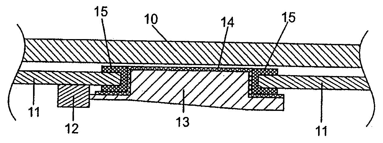
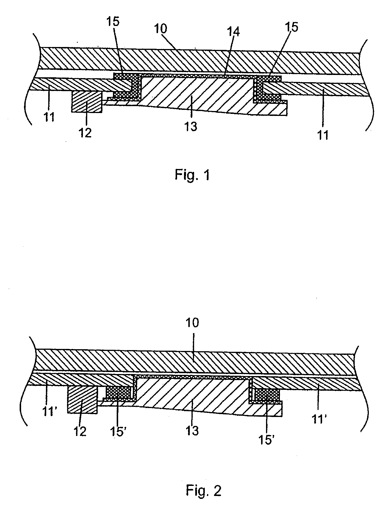
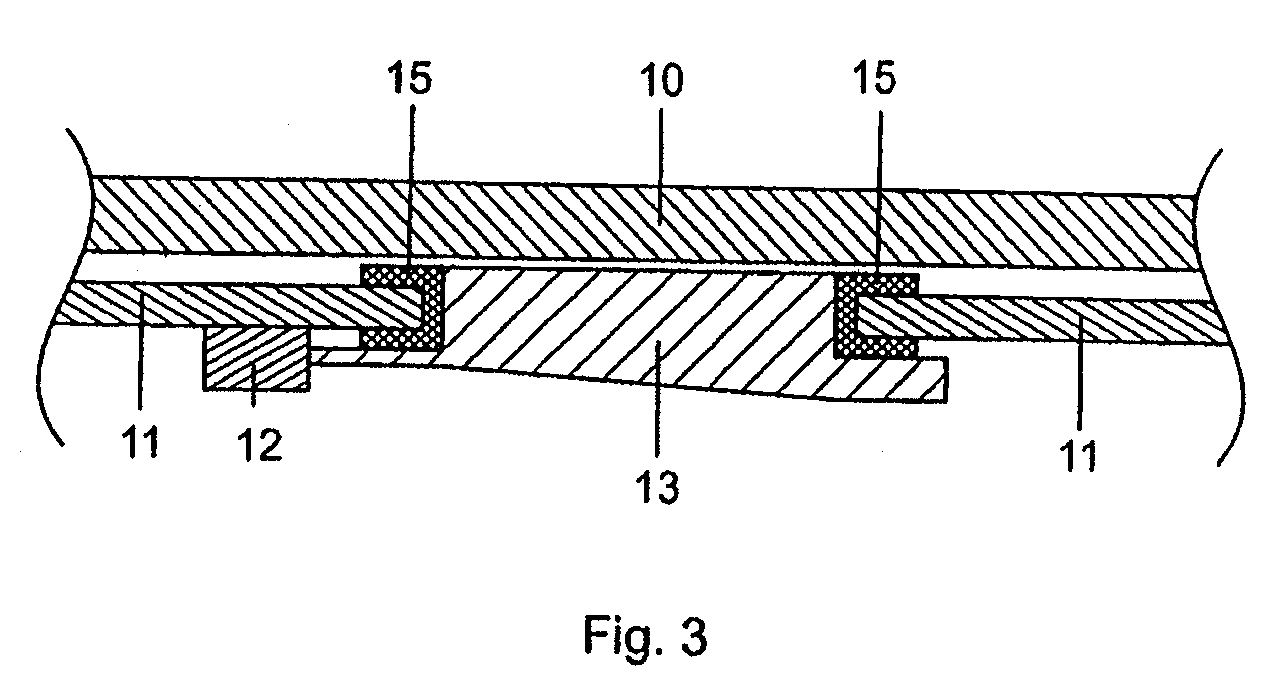
[0013]One aspect of the invention is based on the object of providing a control unit for domestic appliances of the type mentioned initially, which has a very low build height and allows the sensor element to make contact with the circuit board relatively easily.

[0014]This object is achieved in one embodiment by the invention by a control unit according to claim 1. Advantageous and preferred refinements of the invention are the subject matter of the dependent claims and are described in more detail in the following text. The wording of the claims is expressly incorporated by reference in the contents of the description.

[0015]The control unit has at least one sensor element for generating an actuation-dependent sensor signal, at least one luminous means associated with the sensor element, at least one light guide associated with the luminous means for changing the direction of the light entering the light guide with respect to the light emitted by the light guide, and a circuit board...


PUM


Abstract

A control unit comprising a light guide is formed and positioned in a circuit board for providing visual indication to a user of an appliance, such as a cooktop. The light guide receives light from a source, typically in the form of an LED on the circuit board, typically positioned laterally to the light guide, and the light guide receives and directs the light to the user. In some embodiments, the light guide is positioned behind a cover, which may have indicia thereon for providing operating information to the user. Portions of the light guide may be coated with an electrically conductive coating so as to also form a portion of a capacitance touch switch for detecting user input for controlling operation of the appliance.

Description

CROSS REFERENCE TO RELATED APPLICATIONS[0001]This application is a continuation of PCT / EP2007 / 004188, filed May 11, 2007, which in turn claims priority to DE 10 2006 022 965.7, filed on May 12, 2006, the contents of both of which are incorporated by reference.FIELD OF THE INVENTION[0002]The invention relates to a control unit for domestic appliances, in particular for cooktops, for installation behind a cover of the domestic appliance.BACKGROUND OF THE INVENTION[0003]Such control units generally comprise control elements for controlling functions of the domestic appliance. In the case of cooktops, it is possible to provide a control element that operates the respective hot plate of the cooktop, to activate or deactivate the hot plate, and to set the power.[0004]In the case of cooktops, the control unit can be provided within, or on the edge of, the so-called stovetop behind a cover in the form of a glass-ceramic plate. Capacitive sensor elements are generally used as control element...

Claims


Application Information

Patent Timeline
Patent Type & Authority Applications(United States)
IPC IPC(8): H03M11/00
CPCH03K17/962H03K2217/96079H03K2217/960755H03K2017/9602
Inventor ROTH, BERNHARD
Owner E G O ELEKTRO GERAETEBAU GMBH
Why Eureka
Try Eureka