Electrical energy storage cell, electrical energy storage module and method for producing an electrical energy storage cell

A technology for electric energy storage and battery storage, which is applied in secondary battery manufacturing, alkaline battery manufacturing, primary battery to battery grouping, etc. It can solve the problems of increased wear and tear of switchgear, low efficiency of BDI, and increased manufacturing technology to achieve contact resistance. The effect of reducing, optimizing filling, and reducing construction space requirements

Active Publication Date: 2015-04-29
ROBERT BOSCH GMBH
View PDF4 Cites 3 Cited by
  • Summary
  • Abstract
  • Description
  • Claims
  • Application Information

AI Technical Summary

Problems solved by technology

If the energy storage battery is used, for example, in a battery system with an integrated converter, a so-called BDI, the inductive component of the energy storage battery impedance can lead to this inversion at a high operating frequency of the converter. Correspondingly high energy losses in the power electronic switching devices of the
This can therefore lead to increased wear of the switchgear, lower efficiency of the BDI, and increased manufacturing outlay for implementing a cooling system with sufficient cooling capacity

Method used


Image

  • Electrical energy storage cell, electrical energy storage module and method for producing an electrical energy storage cell
  • Electrical energy storage cell, electrical energy storage module and method for producing an electrical energy storage cell
  • Electrical energy storage cell, electrical energy storage module and method for producing an electrical energy storage cell

Examples


Embodiment Construction

[0040] Electrical energy storage batteries within the meaning of the present invention include all devices which are capable of storing electrical energy for a predetermined period of time and delivering it again for another period of time. Energy storage cells within the meaning of the invention include all types of secondary and primary energy stores, in particular capacitive, electrochemical (Faraday) and combined storage types. The period of time considered can here range from a few seconds up to hours, days or years. Electrical energy storage batteries may include, for example, batteries based on lead, zinc, sodium, lithium, magnesium, sulfur or other metals, elements or alloys, lithium ion batteries, lithium polymer batteries, nickel metal hydride batteries, supercapacitors, supercapacitors, electric Capacitor, BatCap or similar system. The function of the electrical energy storage cells encompassed by the invention can be based here on intercalation electrodes, reactio...


PUM


Abstract

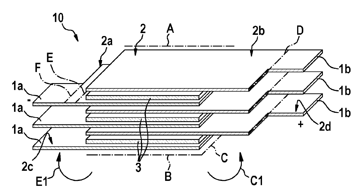
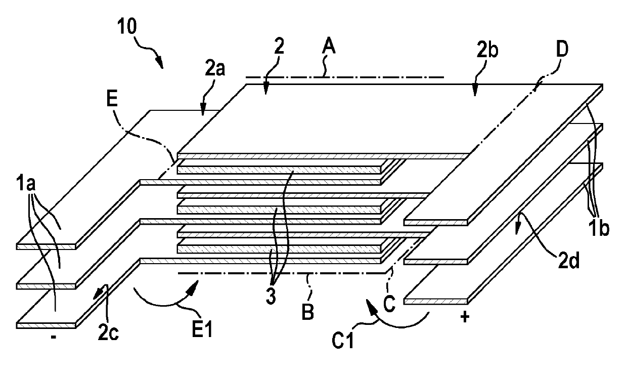
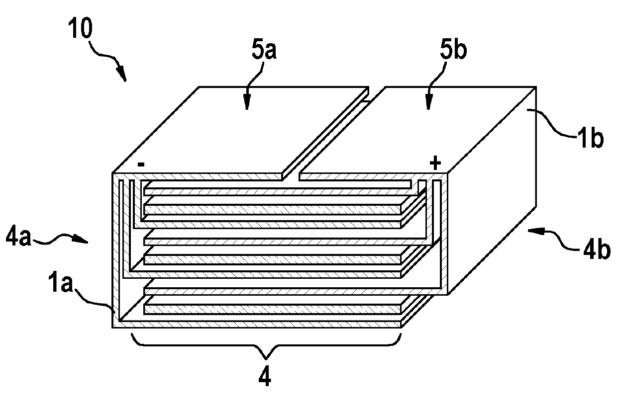
The invention relates to an electrical energy storage cell (10) with a plurality of planar anode foils (1a) which have first storage sections (2) and first arrester sections (2a), and with a plurality of planar cathode foils (1b) which have second storage sections (2) and second arrester sections (2b), the anode foils (1a) and the cathode foils (1b) being stacked plane-parallel relative each other such that the first and section storage sections (2) overlap alternately and form a storage cell stack (4), the first arrester sections (2a) projecting by a first overhang length over a first side face (4a) of the storage cell stack (4) and the second arrester sections (2b) projecting by a second overhang length over a second side face (4b), opposite the first side face (4a), of the storage cell stack (4). The first arrester sections (2a) are folded relative the first storage sections (2) about a first fold line (E) and are oriented in parallel along the first side face (4a) of the storage cell stack (4). The second arrester sections (2b) are folded relative the second storage sections (2) about a second fold line (C) and are oriented in parallel along the second side face (4b) of the storage cell stack (4).

Description

technical field [0001] The invention relates to an electrical energy storage battery, an electrical energy storage module and a method for producing an electrical energy storage battery. Background technique [0002] The DC power is usually taken from or fed into the electrical energy storage battery. Therefore, currently known configurations of energy storage batteries are optimized for the specific energy or power density and ohmic internal resistance of the energy storage battery. [0003] In many applications of electrical energy storage batteries, the storage cells are interconnected into battery modules in a series or parallel arrangement in order to adjust desired output parameters such as overall voltage, voltage range, stored energy or power density. Document DE 10 2010 035 114 A1 discloses, for example, a battery unit having a plurality of battery cells each having battery cells galvanically coupled via bus bars. Document EP 2 413 414 A2 discloses a flat battery ...

Claims


Application Information

Patent Timeline
Patent Type & Authority Applications(China)
IPC IPC(8): H01M2/26H01M10/04H01M10/0585H01M10/28H01M6/46H01M4/70H01M50/533H01M50/54
CPCH01M10/0413H01M10/0436H01M4/70H01M6/46H01M10/281H01M10/0585H01M50/54H01M50/533Y02E60/10Y02P70/50
Inventor M. 凯斯勒A. 蒂芬巴赫
Owner ROBERT BOSCH GMBH
Why Eureka
Try Eureka