Eureka AIR delivers breakthrough ideas for toughest innovation challenges, trusted by R&D personnel around the world.

Wideband dichroic-filter design for LED-phosphor beam-combining

Active Publication Date: 2009-05-07
SEOUL SEMICONDUCTOR
View PDF10 Cites 17 Cited by
  • Summary
  • Abstract
  • Description
  • Claims
  • Application Information

AI Technical Summary

Benefits of technology

[0009]The afore-referenced concurrently filed patent application discloses an LED-phosphor beam-combiner based on a 15° primary incidence angle, with a total angular range of 0-30°. This is a relatively forgiving range of incidence angles, because the wavelength shift of the filter's dichroic performance curve of spectral reflectance (or transmittance) with incidence angle is relatively small at low inciden

Problems solved by technology

The reflected blue light never reaches the phosphor, and the transmitted yellow light never joins the exit beam, so that filter efficiency is the product of both blue and yellow efficiencies, requiring them both to be above √95%=97.5% to achieve 95% overall efficiency, a st

Method used


Image

  • Wideband dichroic-filter design for LED-phosphor beam-combining
  • Wideband dichroic-filter design for LED-phosphor beam-combining
  • Wideband dichroic-filter design for LED-phosphor beam-combining

Examples


Example

DETAILED DESCRIPTION OF THE DRAWINGS

[0050]Reference will now be made in detail to various embodiments of the present invention, examples of which are illustrated in the accompanying drawings. The embodiments are described by way of explanation, and not by way of limitation.

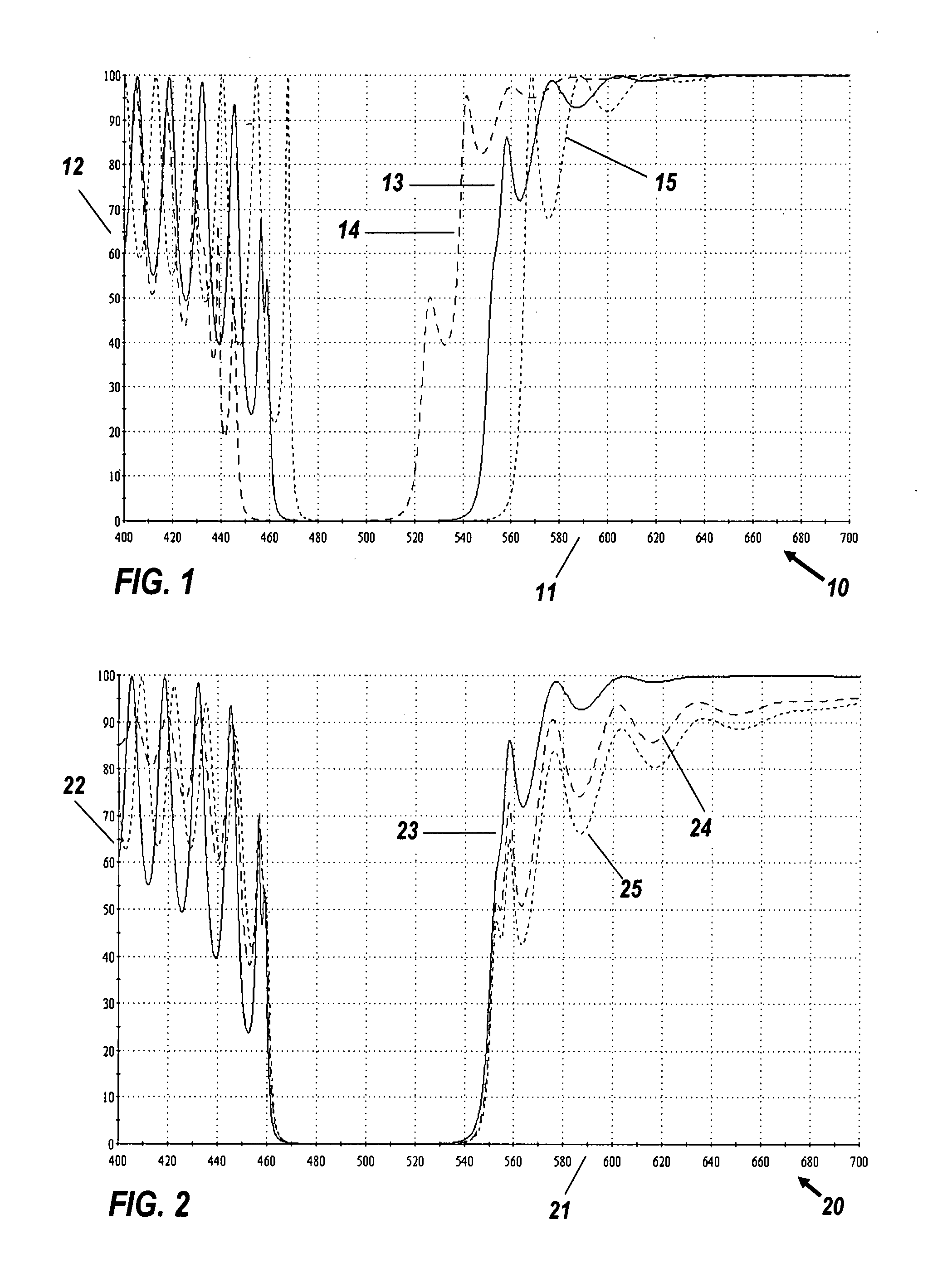
[0051]FIG. 1 shows a spectral transmittance graph 10 with horizontal wavelength scale 11 in nanometers (nm) and vertical transmittance scale 12 in %, for the m=20, 41-layer seed filter (0.75H, 0.5 L, 0.75H)̂20. Solid curve 13 is the transmittance for 15°, dashed curve 14 to its left is for 25°, and dotted curve 15 to its right is for normal incidence. As may be send in FIG. 1, there are minor changes in the shape of the curves, showing that they do more than shift in frequency when the incidence angle is changed.

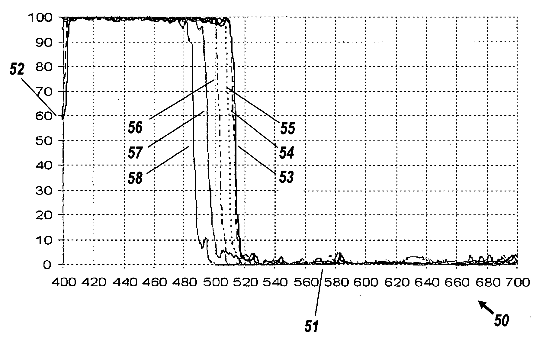
[0052]FIG. 2 shows spectral graph 20 with horizontal wavelength scale 21 in nanometers (nm) and vertical transmittance scale 22 in %, for the m=20, 41-layer seed filter. Solid curve 23 is the transmittance...


PUM


Abstract

A general method is disclosed of designing two-component dichroic short-pass filters operable for incidence angle distributions over the 0-30° range, and specific preferred embodiments are listed. The method is based on computer optimization algorithms for an N-layer design, specifically the N-dimensional conjugate-gradient minimization of a merit function based on difference from a target transmission spectrum, as well as subsequent cycles of needle synthesis for increasing N. A key feature of the method is the initial filter design, upon which the algorithm proceeds to iterate successive design candidates with smaller merit functions. This initial design, with high-index material H and low-index L, is (0.75 H, 0.5 L, 0.75 H)̂m, denoting m (20-30) repetitions of a three-layer motif, giving rise to a filter with N=2m+1.

Description

CROSS REFERENCE TO RELATED APPLICATIONS[0001]This application is filed concurrently with U.S. patent application Ser. No. ______ (docket No. 047654-0018-00-US) of Falicoff et al. for “Optical Manifold,” the disclosure of which is incorporated herein by reference in its entirety.STATEMENT REGARDING FEDERALLY FUNDED RESEARCH AND DEVELOPMENT[0002]This invention was supported in part by the National Energy Technology Laboratory Award No. DE-FC26-05NT42341. The Government may have certain rights in this invention.BACKGROUND OF THE INVENTION[0003]The present invention relates generally to multilayer interference filters with thin-film specifications designed by a computer optimization program. The design methods disclosed herein related specifically to the commercial design package called the Essential Macleod, by the Thin Film Center, Inc. of Tucson Ariz., but could as well be performed by similar software packages or by a customized optimizer program.[0004]In the field of fiber optics, ...

Claims


Application Information

Patent Timeline
IPC IPC(8): G02B5/28
CPCG02B5/285
Inventor FALICOFF, WAQIDI
Owner SEOUL SEMICONDUCTOR
Why Eureka
Eureka Blog
Learn More