Light source device, backlight unit, and liquid crystal display device

a technology of liquid crystal display and backlight unit, which is applied in the direction of lighting support devices, instruments, final product manufacturing, etc., can solve the problem that even color cannot be prevented from being displayed at the corners of the display surface, and achieve the effect of improving the uniformity of luminance and color

Inactive Publication Date: 2009-05-07
SHARP KK
View PDF6 Cites 19 Cited by
  • Summary
  • Abstract
  • Description
  • Claims
  • Application Information

AI Technical Summary

Benefits of technology

[0010]The present invention has been made in view of the above-mentioned state of the art. Preferred embodiments of the present invention provide a light source device, a backlight unit, and a liquid crystal display device, each capable of improving uniformity of a luminance and a color on a display surface.
[0011]The present inventors made various investigations of a light source device including a board on which a plurality of point light sources such as LEDs, connected in series, are formed. The inventors discovered that if a fixed resistor for adjusting a luminance is connected in parallel to the point light source arranged on the end side, an amount of an electric current flowing into the point light source is reduced to decrease an amount of luminescence, and as a result, the corners and other regions of the display surface have substantially the same color tone and the uniformity of the luminance and the color on the display surface can be improved.

Problems solved by technology

However, the results of the study show that even if the above-mentioned measures are taken, uneven color cannot be sufficiently prevented from being displayed at the corners of the display surface because the point light sources such as LEDs have various light-emitting characteristics.

Method used


Image

  • Light source device, backlight unit, and liquid crystal display device
  • Light source device, backlight unit, and liquid crystal display device
  • Light source device, backlight unit, and liquid crystal display device

Examples


first preferred embodiment

[0056]Steps of assembling a liquid crystal display device in accordance with the first preferred embodiment of the present invention are mentioned below.

Production of LED Backlight Module (Light Source Device)

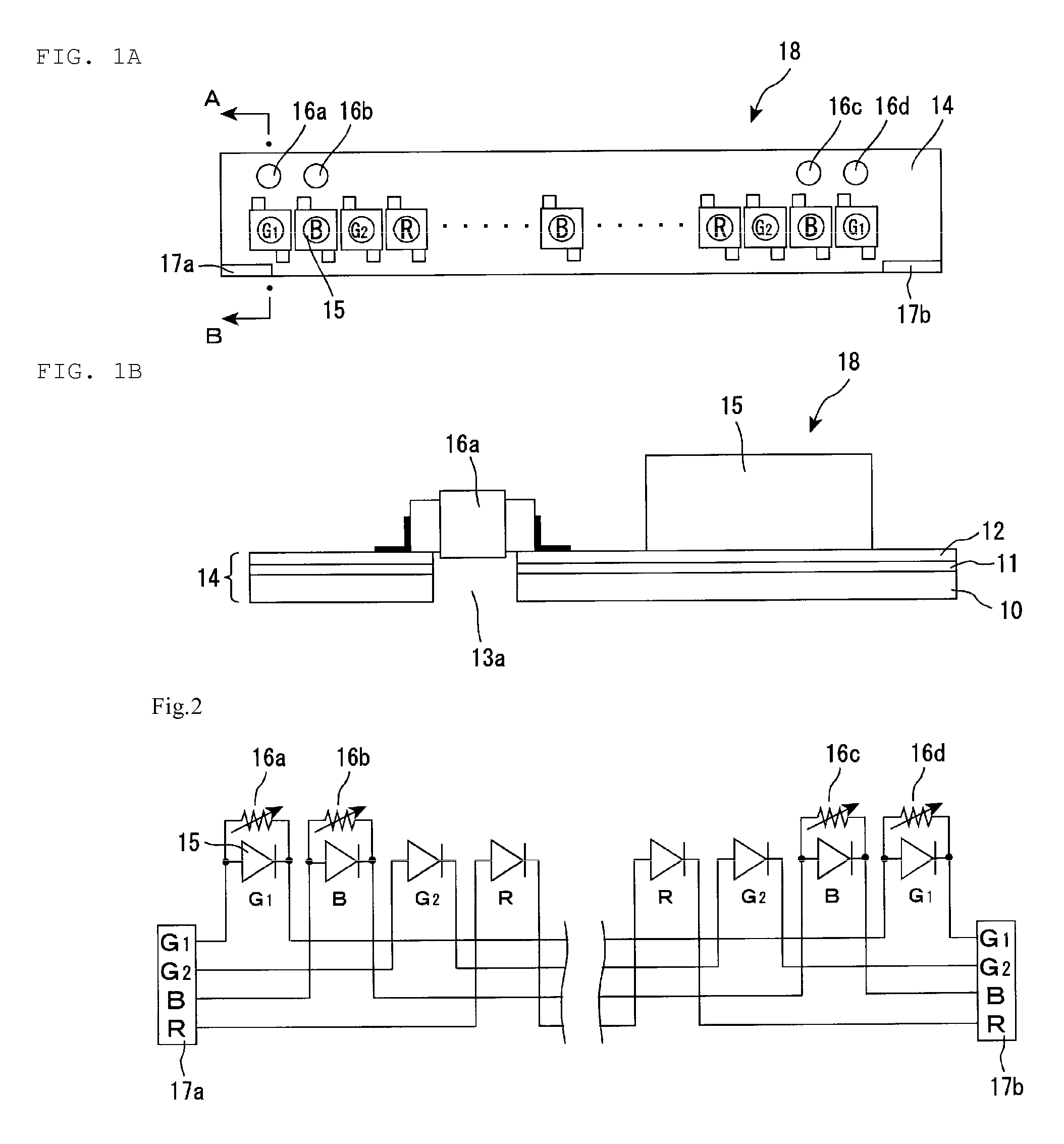
[0057]FIG. 1A is a planar view schematically showing a configuration of an LED backlight module in accordance with the first preferred embodiment. FIG. 1B is a cross sectional view schematically showing the LED backlight module taken along line A-B in FIG. 1A.

[0058]On an aluminum board 10, a transparent insulating layer 11 with a thickness of about 80 μm, for example, was formed. Thereon, a copper foil layer 12 with a thickness of about 70 μm, for example, was formed by printing. Then, the outline of the stacked body was shaped by a punching process and simultaneously, a through-hole 13a was formed at a position where a variable resistor was to be mounted. As a result, a flexible printing circuit (FPC) 14 was completed.

[0059]Then, light-emitting diodes (LEDs) 15, variable resis...

second preferred embodiment

[0067]Steps of assembling a liquid crystal display device in accordance with the present preferred embodiment are described below. A direct LED backlight unit was used as the LED backlight unit in the present preferred embodiment.

Production of LED Backlight Module (Light Source Device)

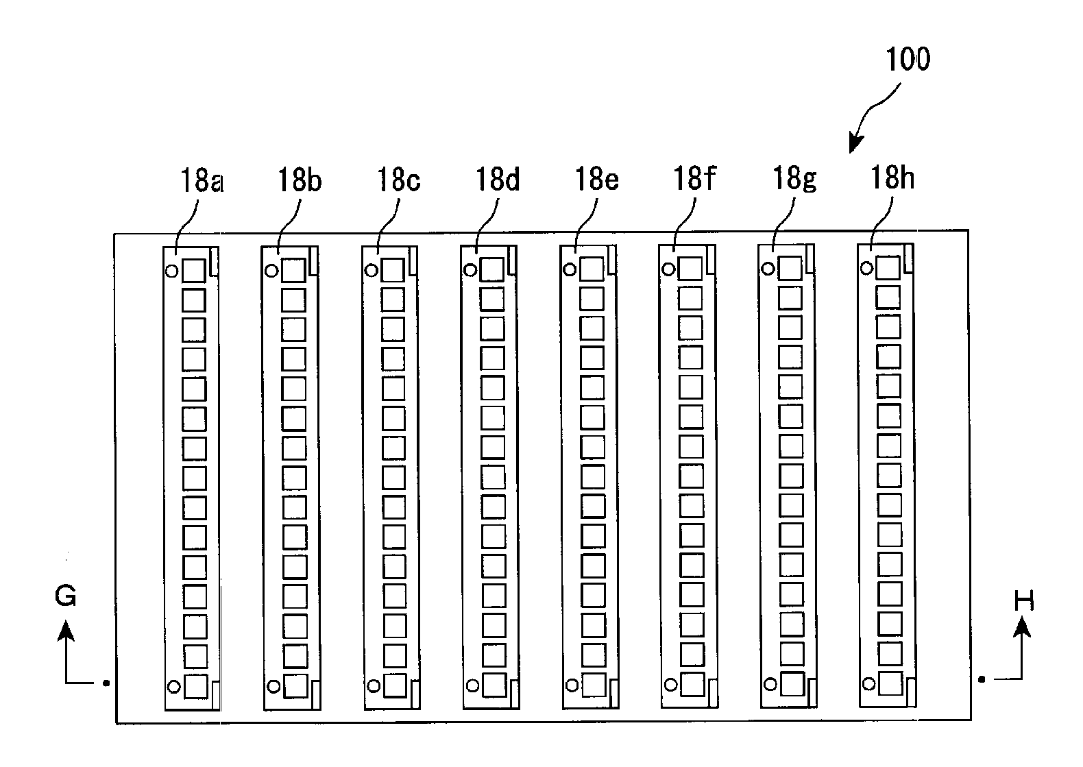
[0068]FIG. 4A is a planar view schematically showing a configuration of an LED backlight module in the second preferred embodiment. FIG. 4B is a cross-sectional view schematically showing the LED backlight module taken along line E-F in FIG. 4A. FIG. 5 is a view schematically showing a circuit for the LED backlight module in the second preferred embodiment.

[0069]The LED backlight module in the present preferred embodiment was produced in the same manner as in the first preferred embodiment, except that only G1-LEDs at the right and left ends were connected in parallel to the variable resistors 16a and 16b, respectively, as shown in FIGS. 4A, 4B, and 5.

[0070]The variable resistors 16a and 16b were dispo...


PUM

PropertyMeasurementUnit
thicknessaaaaaaaaaa
thicknessaaaaaaaaaa
areaaaaaaaaaaa

Abstract

A light source device, a backlight unit, and a liquid crystal display device are each capable of improving uniformity of a luminance and a color of a display surface. The light source device includes a board; a plurality of point light sources arranged on a surface of the board and connected in series; and a variable resistor, wherein the variable resistor is disposed on the surface on which the plurality of point light sources are arranged of the board; at least one point light source arranged on an end side among the plurality of point light sources is connected in parallel to the variable resistor; and the board has a through-hole in a region where a variable resistor is located.

Description

[0001]This Nonprovisional application claims priority (under the Paris Convention and the domestic law in the country to be entered into the national phase) of Japanese Patent Application No. 2005-282816 filed in Japan on Sep. 28, 2005, the entire contents of which are hereby incorporated by reference.BACKGROUND OF THE INVENTION[0002]1. Field of the Invention[0003]The present invention relates to light source devices, backlight units, and liquid crystal display devices. More specifically, the present invention relates to a light source device that is used as a component of a backlight unit mounted for a display device such as a liquid crystal display device. The present invention also relates to a backlight unit, and a liquid crystal display device.[0004]2. Description of the Related Art[0005]A liquid crystal display device is a non-self-luminous display, and therefore, it generally includes a backlight unit on the back surface of a liquid crystal display panel in order to improve d...

Claims


Application Information

Patent Timeline
Patent Type & Authority Applications(United States)
IPC IPC(8): G02F1/13357F21V21/00G09F13/08
CPCG02B6/0031G02B6/0055G02B6/0068G02B6/0083G02F1/133603G09G3/3413H05K2201/10196H05B33/083H05K1/181H05K2201/09072H05K2201/10022H05K2201/10106G09G2320/0233H05B45/48Y10S362/80Y02P70/50
Inventor HAMADA, TETSUYA
Owner SHARP KK
Why Eureka
Try Eureka