Objective Lens Actuator

a technology of objective lens and actuator, which is applied in the direction of optical recording head, data recording, instruments, etc., can solve the problems of troublesome control of the objective lens actuator, and achieve the effect of bringing in unwanted resonance and high data transfer ra

Inactive Publication Date: 2009-05-07
HITACHI MEDIA ELECTORONICS CO LTD
View PDF4 Cites 0 Cited by
  • Summary
  • Abstract
  • Description
  • Claims
  • Application Information

AI Technical Summary

Benefits of technology

[0016]According to the present invention mentioned above, it is possible to provide an optical pickup for achieving high speeding of the data transfer rate, wi

Problems solved by technology

The elasticity originally owned by the wire is made between a distance from the wire support part at the lens holder and the wire support part at the wire support member mentioned above,

Method used


Image

  • Objective Lens Actuator
  • Objective Lens Actuator
  • Objective Lens Actuator

Examples


embodiment 1

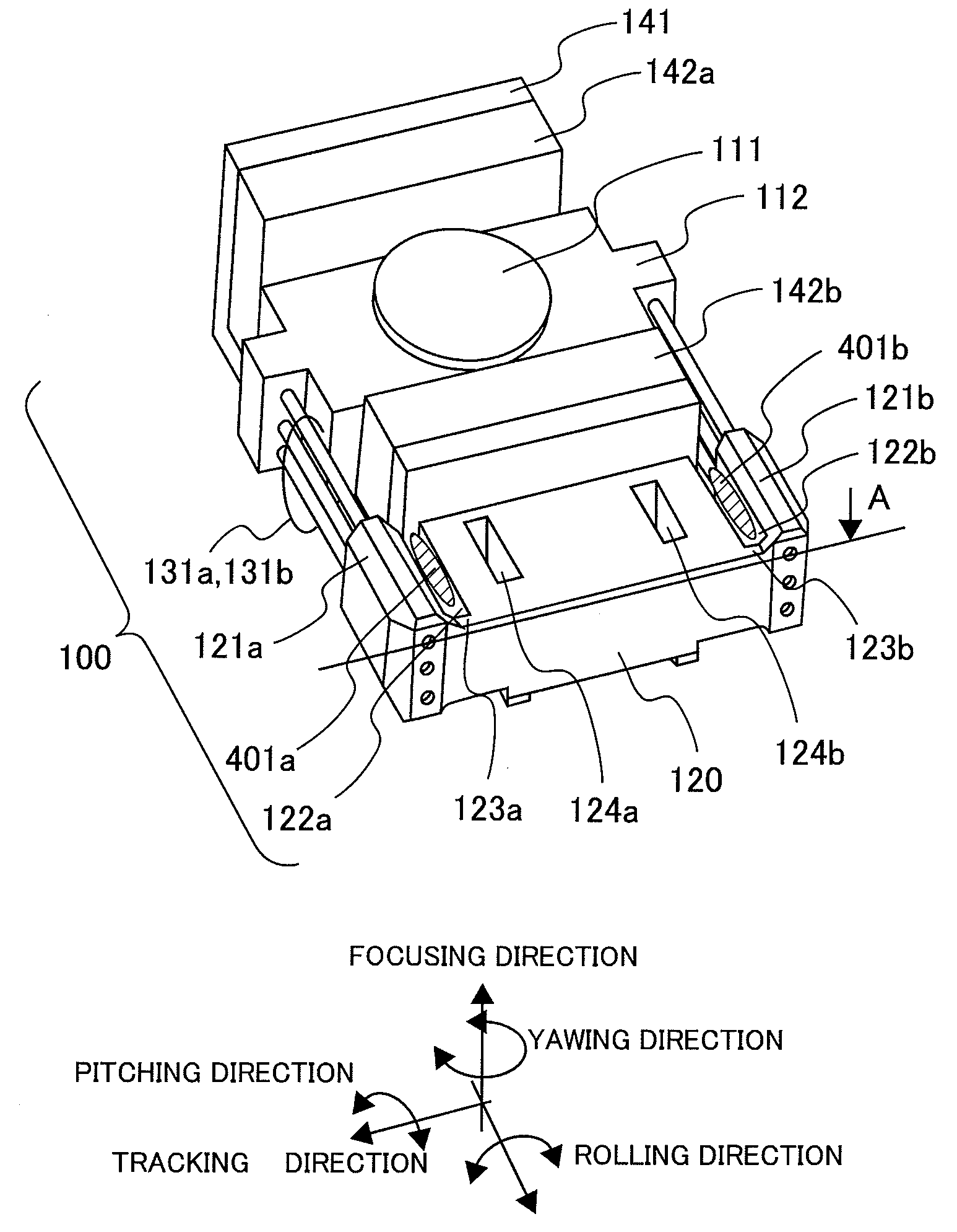
[0027]Explanation will be made on a first embodiment according to the present invention, by referring to FIGS. 1, 2, 3, 4 and 7.

[0028]FIG. 1 is an outlook view for showing an objective lens actuator, according to the present embodiment.

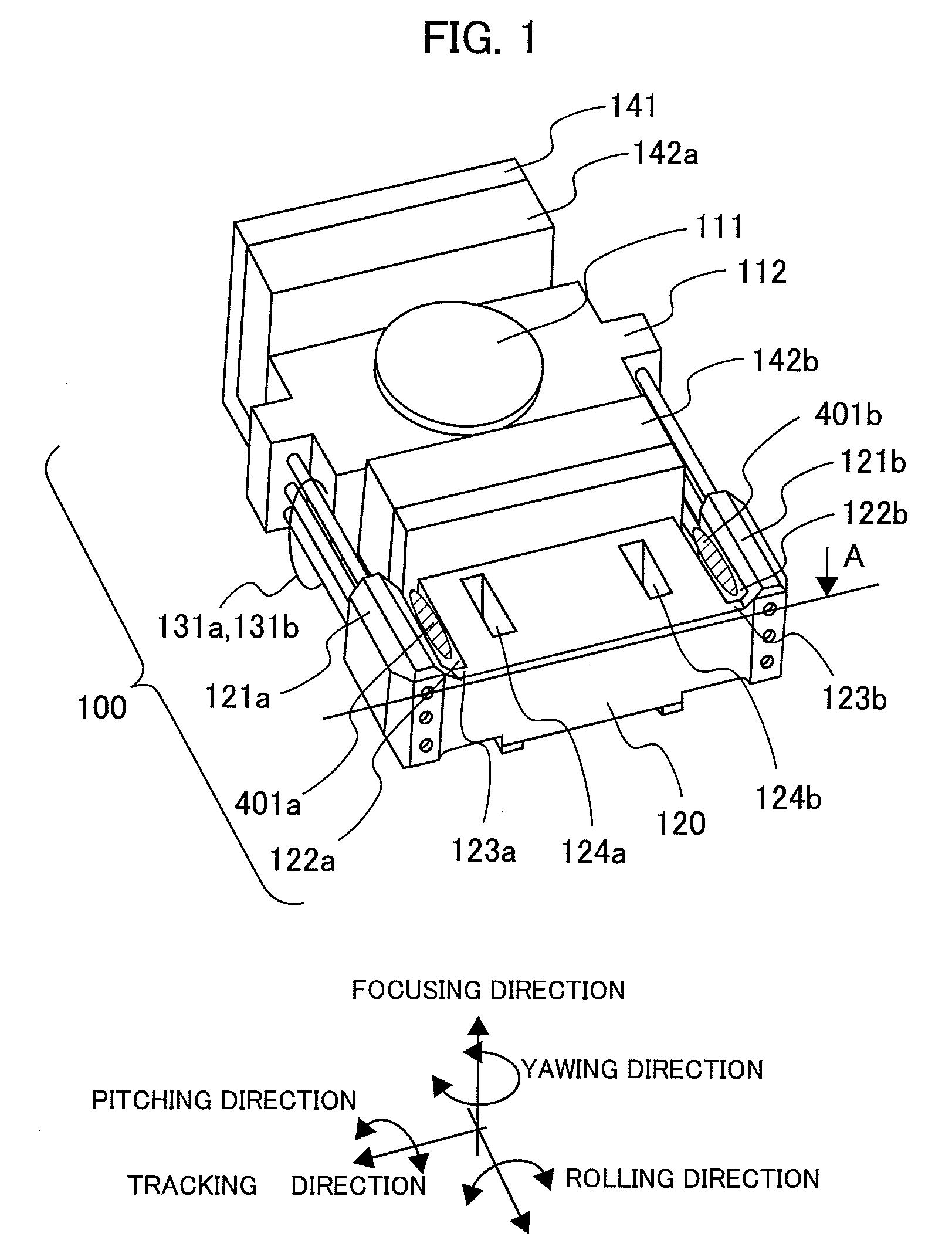
[0029]FIG. 2 is a A-A cross-section view in FIG. 1, for showing the vicinity of an elastic support member support part, according to the present embodiment.

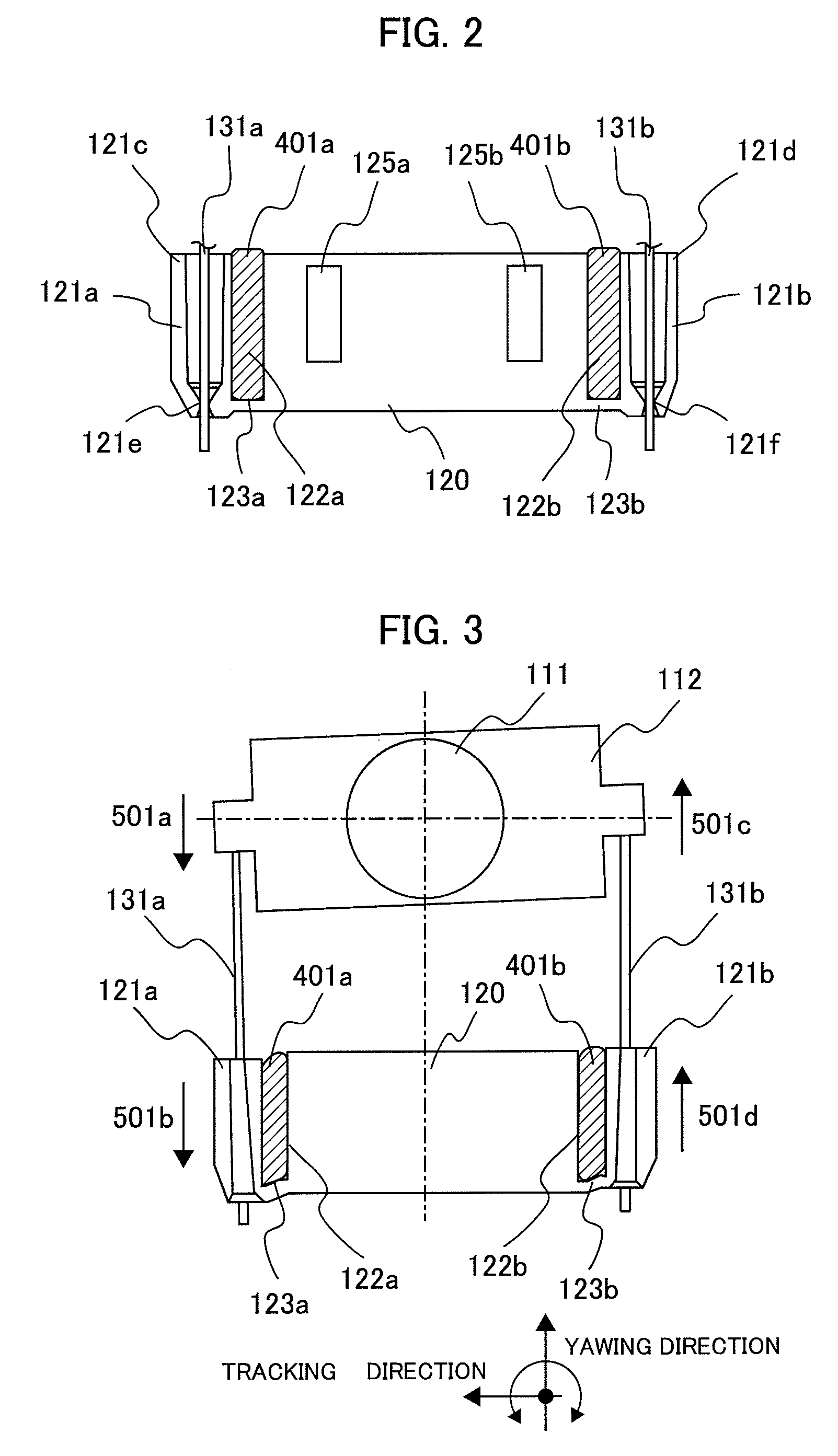
[0030]FIG. 3 is a view for showing the operations when a yawing vibration is generated, according to the present embodiment.

[0031]FIG. 4 is a view for showing the operations when a pitching vibration is generated, according to the present embodiment.

[0032]FIG. 7 is a graph for showing a relationship between a notch distance of the elastic support member support part and a phase disorder value of a yawing vibration.

[0033]The characteristic of the present embodiment lies in that a cutting area of a square shape is provided along with an axial direction of an elastic support member, within a member fo...

embodiment 2

[0050]FIG. 5 is a drawing for showing an outlook of mounting the objective lens actuator according to the present embodiment onto an optical pickup case.

[0051]The feature of the present embodiment lies in that a projection part formed on the optical pickup is inserted into a hole, which is provided on the objective lens actuator.

[0052]Hereinafter, the structures of the present embodiment will be shown.

[0053]In FIG. 5, the objective lens 111 is attached on the lens holder 112. The lens holder 112 is elastically supported on the wire support part 120, through the wires 131a and 131b, as the elastic support members, and is movable.

[0054]In this manner, the objective lens 111 can focus the laser light onto the disc not shown in the figure. The lens holder 112 can move or displace in the movable directions, i.e., the focus, tracking and radial tilt directions, largely, but as will be mentioned later, a part of the wire support part 120 connecting with the wire can also move or displace i...

embodiment 3

[0060]Explanation will be made on a third embodiment of the present invention, by referring to FIG. 6.

[0061]FIG. 6 is a view for showing the connection part between the wire support part and the optical pickup case, enlargedly.

[0062]The feature of the present embodiment lies in that an adhesive having attenuation or damping function is disposed at the connection part between the wire support part and the optical pickup case according to the embodiment 2.

[0063]Explanation will be made on the present embodiment by referring to FIG. 6.

[0064]In FIG. 6, the connection part between the wire support part 120 and the optical pickup case 200 is connected by an insertion hole 125a, which is provided on the wire support part 120, and a projection part 201a, which is provided on the optical pickup case 200. The size of the insertion hole 125a formed is determined to be small comparing to the projection part 201a. Accordingly, when connecting the wire support part 120 with the optical pickup cas...


PUM


Abstract

An objective lens actuator in an optical pickup, having a semiconductor laser diode, electro-optic parts, such as a lens or the like, as well as, the objective lens actuator, etc., in a case, comprises: a holder, which mounts an objective lens and a coil thereon, as being a movable part; a magnetic circuit part, which is made up with a magnet for magnetically driving said holder and a yoke; a plural number of elastic support parts which elastically supports said holder; and a support part, which supports other ends of said elastic support parts, wherein said support part has a part, which is cut open in parallel with the elastic support parts, between said elastic support parts, and has a through hole, in which said elastic support part passes through for each of said elastic support parts, and thereby to provide the objective lens actuator for lowering the unwanted vibration mode of the objective lens, and also enabling a stable control thereof.

Description

BACKGROUND OF THE INVENTION[0001]The present invention relates to an objective lens actuator of an optical pickup, for conducting reading / writing from / onto a disc within an optical disc apparatus, etc., and it further relates to an optical pickup and also an optical disc apparatus comprising the objective lens actuator therein.[0002]In recent years, with an optical disc apparatus is achieved speed-up of the data transfer rate through high-density thereof, and this is remarkable, in particular, in a field of an optical disc apparatus of a thin-type, i.e., being called “a slim type”. It is the optical pickup that conducts data recording / reproducing within the optical disc apparatus. Thus, within the optical pickup, the objective lens actuator is a device for driving an objective lens for condensing or focusing lights on a recording surface of the optical disc, in the focusing direction (i.e., directions for approaching / separating to / from an optical disc surface), the tracking directio...

Claims


Application Information

Patent Timeline
IPC IPC(8): G11B7/12
CPCG11B7/0933G11B7/0932
Inventor SATOU, YOSHIHIROKIMURA, KATSUHIKOITOU, TETSUOYAMADA, SOUICHIROU
Owner HITACHI MEDIA ELECTORONICS CO LTD
Why Eureka
Try Eureka