
Information storage device and storage media

a technology of information storage and storage media, applied in the field of information memory apparatus, can solve the problems of light dispersion, light absorption in unselected layers, and the signal-to-noise ratio of light-sensor devices will be lowered

Inactive Publication Date: 2009-05-07
HITACHI LTD
View PDF5 Cites 7 Cited by
  • Summary
  • Abstract
  • Description
  • Claims
  • Application Information

AI Technical Summary

Benefits of technology

The present invention is an information memory apparatus that includes an illumination unit, a memory unit, a reading unit, and a computation unit. The apparatus uses a memory medium with a memory area and a plurality of memory cells to store data using a difference in transmissivity for light rays or a difference in light emission characteristics. The light rays are incident on the memory medium and the data is read using the reading unit. The apparatus is designed to accurately analyze the data and prevent signal-to-noise ratio issues caused by dispersion of light in unselected layers. The invention solves the problem of accurately reading the sectional information in the memory medium and provides a better method for writing data into the memory medium.

Problems solved by technology

If a layer which is far from the light-sensor device is selected, however, the dispersed light passes through layers which are not selected and consequently absorption of light in the unselected layers and dispersion of light by the unevenness are caused.
Therefore, there is a possibility that the signal-to-noise ratio in the light-sensor device will be lowered and the signal readout cannot be conducted.
In the embodiment described in JP-A-06-076374, the laser beam is incident in the diameter direction of the cylinder and consequently the problem that the signal-to-noise ratio of the signal is lowered when the length in the rotation axis direction of the cylinder is prolonged is not posed.

Method used


Image

  • Information storage device and storage media
  • Information storage device and storage media
  • Information storage device and storage media

Examples


Embodiment Construction

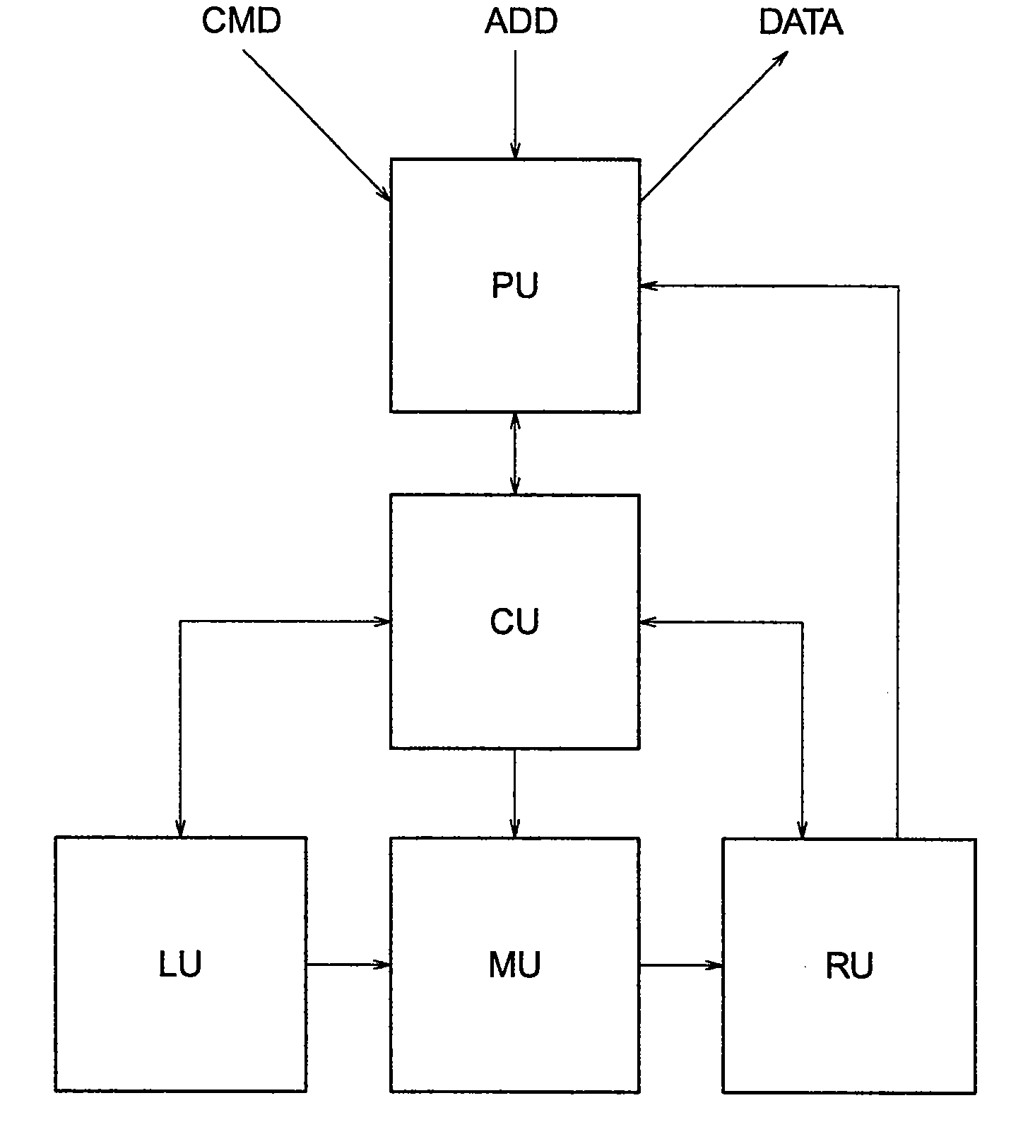
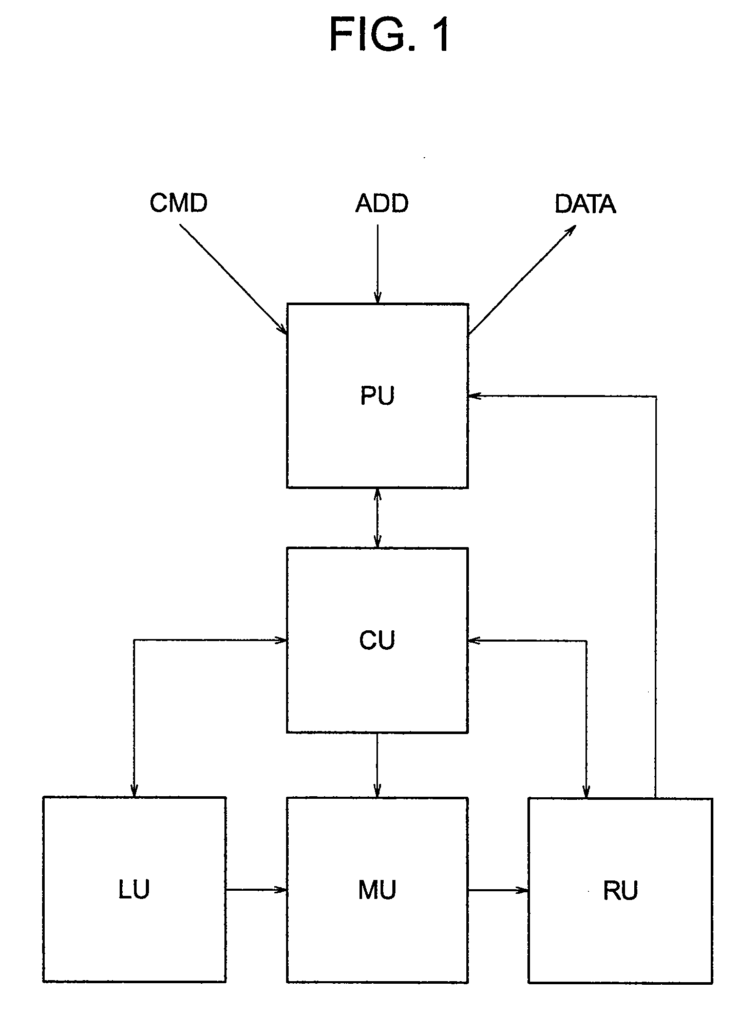
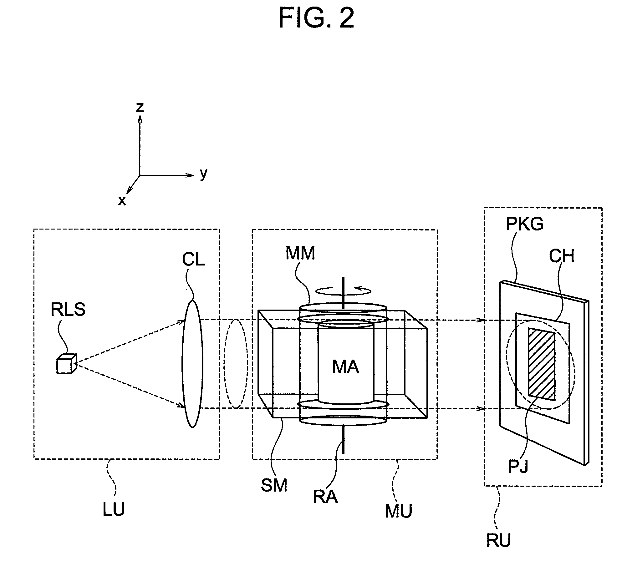
[0043]Hereafter, embodiments of the present invention will be described in detail with reference to the drawings. Throughout all drawings for explaining the embodiments, the same members are denoted by like reference characters as a general rule and their repeated description will be omitted. The drawings and description of the present invention are simplified with the object of illustrating elements needed to understand the present invention clearly. At the same time, other elements considered to be well known are excluded for brevity. It will be appreciated by those skilled in the art that other elements which are not illustrated are desired or needed to implement the present invention. Since such elements are well known in the art and are not helpful to better understanding of the present invention, however, such elements will not be described in the present specification.

[0044]FIG. 1 and FIG. 2 show a first embodiment of an information memory apparatus according to the present i...


PUM

PropertyMeasurementUnit
diameteraaaaaaaaaa
diameteraaaaaaaaaa
diameteraaaaaaaaaa

Abstract

In an information memory apparatus having minute areas for storing information arranged in x, y and z directions three-dimensionally, parallel rays are irradiated to a memory area MA in a direction perpendicular to a z-axis to take projection images of the memory area MA while rotating the memory area MA around the z-axis little by little. The light rays irradiated at this time have a size which covers at least a direction of an x-y plane of the memory area. A computation unit PU finds data and addresses of minute areas distributed three-dimensionally by performing computation based upon the principle of computer tomography on the projection images. As for data writing, a change is given to optical transmissivity or light emission characteristics by irradiating laser light focused by a lens OL placed outside the memory area to a desired minute area and causing heat denaturation within the pertinent minute area.

Description

INCORPORATION BY REFERENCE[0001]The present application claims priority from Japanese application JP2007-284665 filed on Nov. 1, 2007, the content of which is hereby incorporated by reference into this application.BACKGROUND OF THE INVENTION[0002]The present invention relates to an information memory apparatus and in particular to a memory apparatus suitable for storing information in a three-dimensional form.[0003]Devices which handle digital information such as images and voices have made rapid advances in performance improvement. In keeping therewith, information memory apparatuses have also made great advances. As representative information memory apparatuses, there are semiconductor memories, hard disks and optical disks. They are basically obtained by arranging information storing elements in a two-dimensional form. Higher integration and lower cost of them have been made mainly relying upon advance of the microprocessing technology. However, it has also become gradually diffi...

Claims


Application Information

Patent Timeline
Patent Type & Authority Applications(United States)
IPC IPC(8): G11B9/10G11B7/135
CPCG11B7/24006G11B7/0025
Inventor WATANABE, TAKAOSHINTANI, TOSHIMICHIMAEDA, TAKESHIHIROTSUNE, AKEMISEKIGUCHI, TOMONORI
Owner HITACHI LTD
Learn More