Optical connector

Active Publication Date: 2009-05-07
THE FUJIKURA CABLE WORKS LTD
View PDF2 Cites 44 Cited by
  • Summary
  • Abstract
  • Description
  • Claims
  • Application Information

AI Technical Summary

Benefits of technology

[0013]An object of the present invention is to provide an optical connector easy to increase in cores, inexpensive to manufacture, providing good positional accuracy of optical f

Problems solved by technology

(1) Shrinkage deformation (warpage) occurs when resin shrinks upon curing in the course of resin molding, Positional accuracy of the optical fiber insertion holes tends to be degraded by this shrinkage deformation (warpage).
(2) The lateral width of a standard MT optical connector is fixed. Accordingly, the number of the optical fib

Method used


Image

  • Optical connector
  • Optical connector
  • Optical connector

Examples


Example

First Embodiment

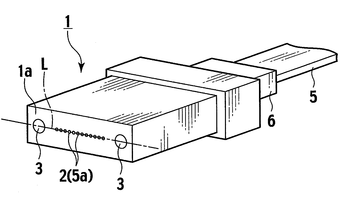
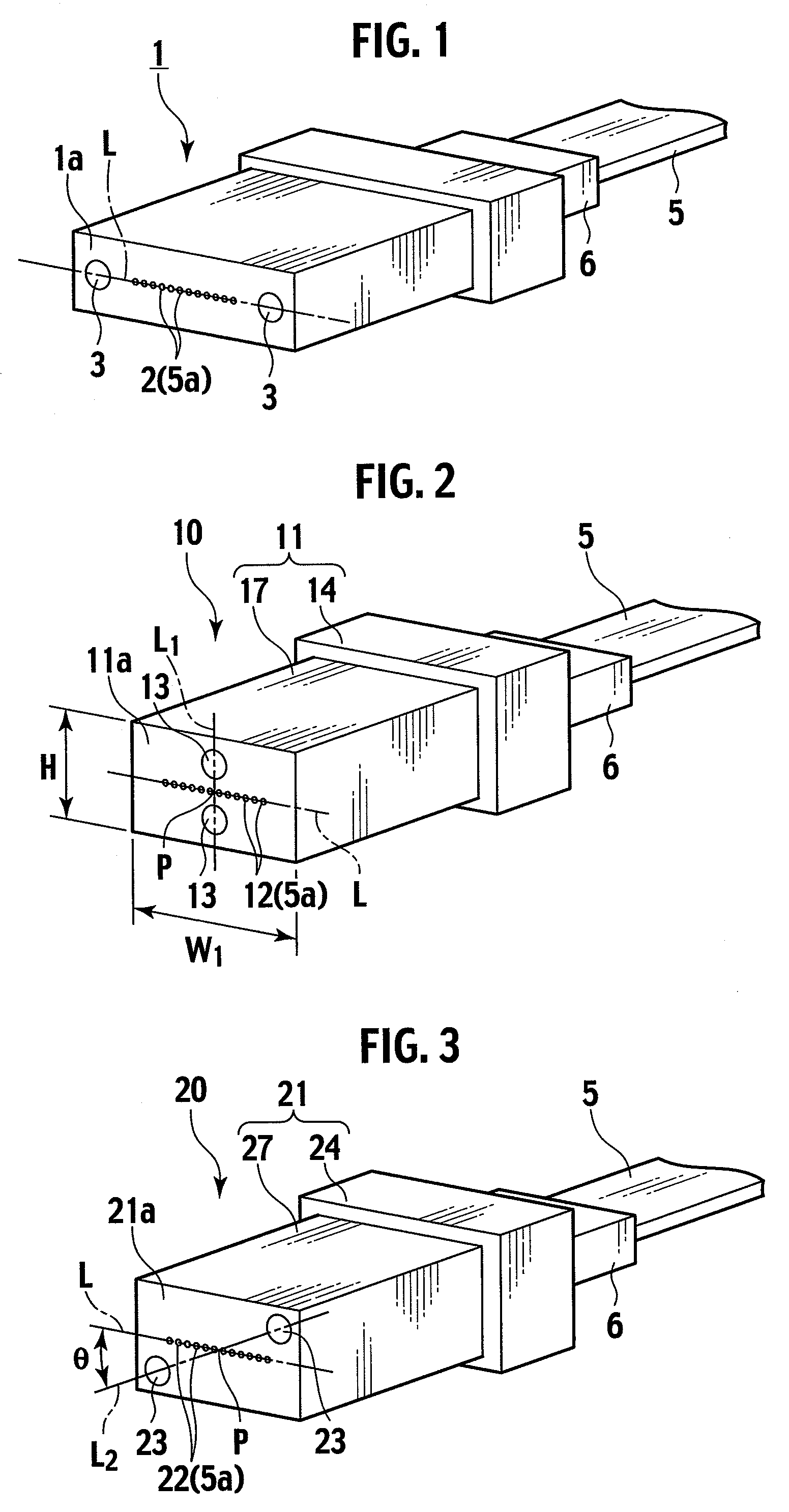
[0035]A first embodiment of the present invention will be described with reference to FIG. 2. An optical connector 10 of this embodiment is a multi-core optical connector of a fitting pin positioning type which is integrally formed of resin. As shown in FIG. 2, multiple optical fiber insertion holes 12 arranged in a lateral line are opened on a connection end surface 11a of a ferrule body 11 which serves as a connection surface with an opponent optical connector (not shown). Two fitting holes 13 for positioning are formed above and below these optical fiber insertion holes 12 so as to sandwich the row of the optical fiber insertion holes 12 therebetween. A diameter of each fitting hole 13 is larger than those of the optical fiber insertion holes 12. A straight line L is a straight line that horizontally passes through the center of the connection end surface 11a. The center of each of the optical fiber insertion holes 12 is located on the straight line L. The two fit...

Example

[0049]A second embodiment of the present invention will be described with reference to FIG. 3. In FIG. 3, constituents that are common to those in FIG. 2 will be designated by the same reference numerals.

[0050]As shown in FIG. 3, an optical connector 20 according to the second embodiment is an optical connector similar to the first embodiment. Multiple optical fiber insertion holes 22 arranged in one lateral row and two fitting holes 23 having a larger diameter than that of the optical fiber insertion holes 22 are formed on a connection end surface 21a of a ferrule body 21. The two fitting holes 23 for positioning are formed on mutually vertically opposite sides relative to a straight line L and near corners of the connection end surface 21a. These two fitting holes 23 are formed in positions that are point-symmetrical with respect to a center P of the row. Moreover, the centers of the two fitting holes 23 are located on a straight line L2 that defines a predetermined angle θ other ...

Example

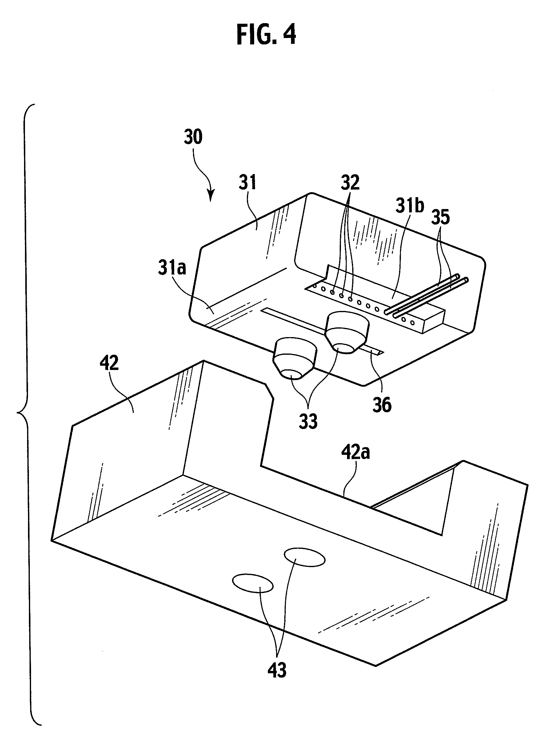
[0053]A third embodiment of the present invention will be described with reference to FIG. 4 to FIG. 7. An optical connector 30 according to the third embodiment is an optical connector of an optical path change type. An optical connector 30 according to the third embodiment includes a reflector provided on a ferrule body 31. In FIG. 4, a recess 36 functioning as the reflector is formed as an example. The reflector couples optical axes of light propagated through multiple optical fibers 35 fitted to the ferrule body 31 and arranged side by side in one row (in the vertical direction of FIG. 5) at constant intervals, with optical axes of multiple optical elements 41 provided laterally in one row (in the vertical direction of FIG. 5) with constant intervals on a fitting surface 42a of a positioning table 42 on which the ferrule body 31 is mounted. Specifically, the reflector reflects the light so as to guide the light from the optical elements 41 to the optical fibers 35 or to guide th...


PUM


Abstract

An optical connector of a fitting pin positioning type includes multiple optical fiber insertion holes arranged in one row and fitting holes or fitting pins. The fitting holes or the fitting pins for positioning are respectively disposed on mutually opposite sides of a straight line connecting centers of the optical fiber insertion holes and are located point-symmetrically with respect to a center of the row of the entire optical fiber insertion holes arranged on the straight line.

Description

CROSS REFERENCE TO RELATED APPLICATION[0001]This application claims the benefit of priority under 35 U.S.C. §119 to Japanese Patent Application Nos. 2007-280312 filed on Oct. 29, 2007 and 2008-234026 filed on Sep. 11, 2008, the entire contents of which are incorporated by reference herein.BACKGROUND OF THE INVENTION[0002]1. Field of the Invention[0003]The present invention relates to an optical connector having a fitting protrusion or a fitting recess used for positioning.[0004]2. Description of the Related Art[0005]Japanese Patent Application Laid-Open Publication No. 2007-033491 discloses a conventional optical connector 1 which is positioned by use of fitting pins. This optical connector 1 is shown in FIG. 1.[0006]The optical connector 1 is formed by resin molding. On a front surface 1a of the optical connector 1, multiple optical fiber insertion holes 2 are arranged in one row, and fitting holes 3 are disposed on both sides of the row of the optical fiber insertion holes 2.[0007...

Claims


Application Information

Patent Timeline
IPC IPC(8): G02B6/36
CPCG02B6/3885G02B6/4292G02B6/4249G02B6/4214
Inventor NISHIMURA, AKITOFUJIWARA, KUNIHIKOOHTA, TATSUYASASAKI, KENJIHAYASHI, YUKIO
Owner THE FUJIKURA CABLE WORKS LTD
Why Eureka
Try Eureka