Refrigerant compressor

Active Publication Date: 2009-05-07
DANFOSS COMPRESSORS +1
View PDF8 Cites 0 Cited by
  • Summary
  • Abstract
  • Description
  • Claims
  • Application Information

AI Technical Summary

Benefits of technology

[0013]Preferably, a piston driven by a motor is arranged in the cylinder, and the mating thread element interacts with threaded bolts, which are located at the side of the cylinder facing away from the motor. In order to simplify the following explanation, the threaded bolts located at the side of the cylinder facing away from the motor are called “upper threaded bolts”, and the other threaded bolts are called “lower threaded bolts

Problems solved by technology

Also with a very accurate manufacturing of the cylinder, however, the manufacturing of the threaded bores in the cylinder block may again cause deformations of the cylinder, which may harm the tightness of the bearing of the piston in the cylinder and thus the efficie

Method used


Image

  • Refrigerant compressor
  • Refrigerant compressor

Examples


Example

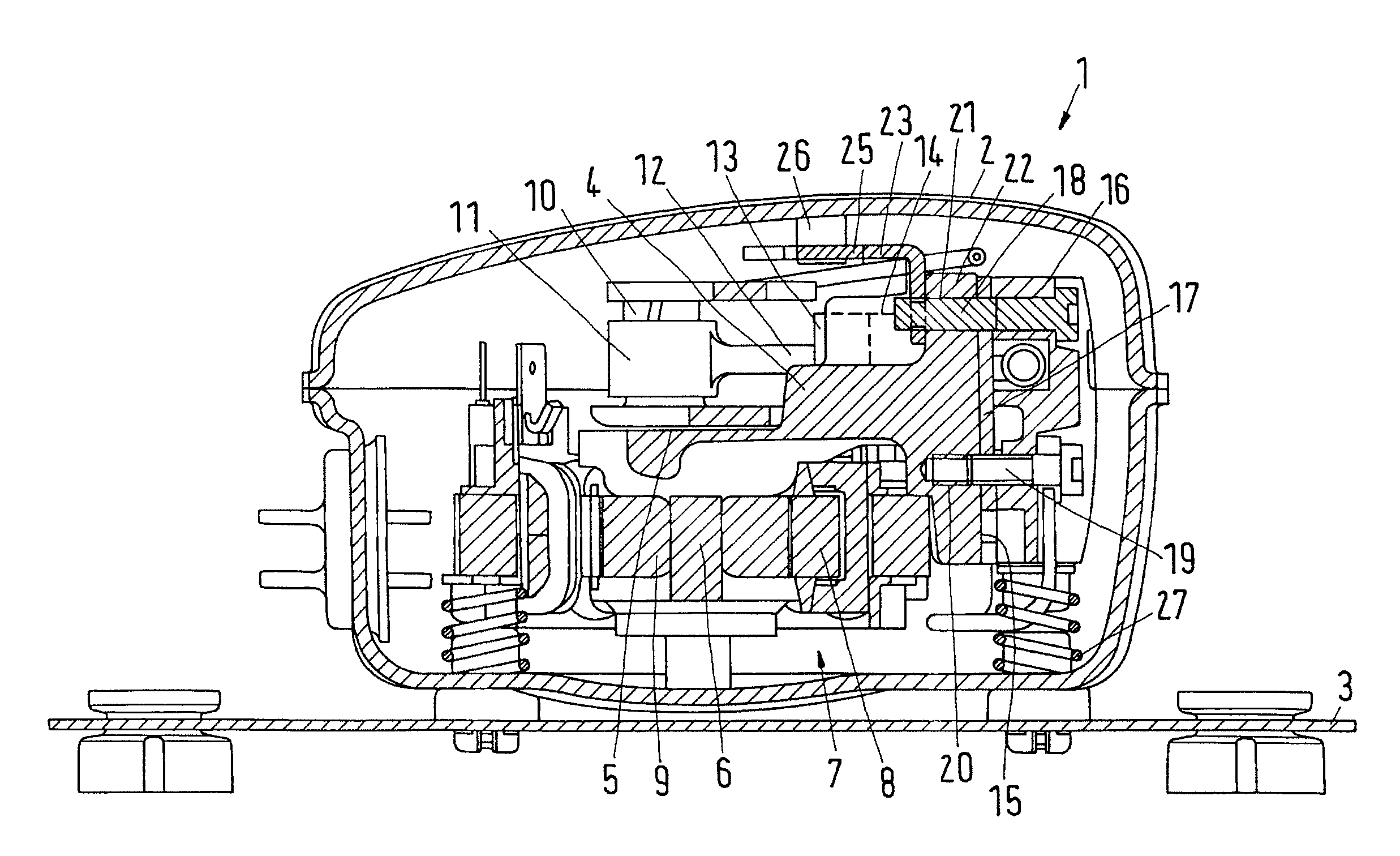
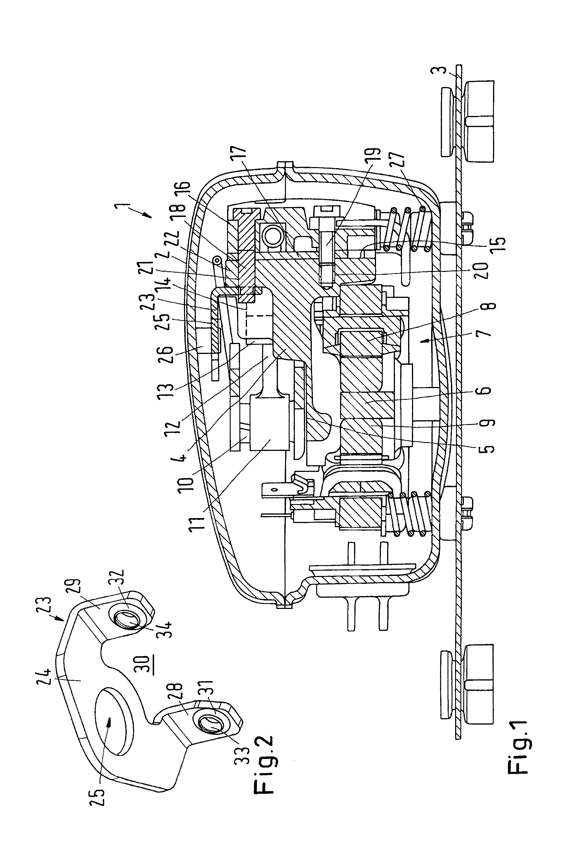
[0017]A refrigerant compressor 1 has a hermetically enclosed housing 2, by means of which it can be built into a refrigeration appliance 3.

[0018]A cylinder block 4 is arranged in the housing 2. The cylinder block 4 forms a bearing5 for a shaft 6 of a motor 7, whose stator 8 is connected to the cylinder block 4. A rotor 9 of the motor 7 is unrotatably connected to the shaft 6. At its upper end, the shaft 6 has a crank pin 10, on which a crank eye 11 of a connecting rod 12 is supported. The other end of the connecting rod 12 is connected to a piston 13 and converts the rotary movement of the shaft into a reciprocating movement of the piston 13.

[0019]The piston 13 is arranged in a cylinder 14, which is formed in the cylinder block 4. Here, the cylinder 14 is drawn with dotted lines.

[0020]The cylinder block 4 has a front side 15, at which a cylinder head 16 is arranged, which covers the cylinder 14. A cylinder head sealing 17 is arranged between the cylinder head 16 and the cylinder blo...


PUM


Abstract

The invention concerns a refrigerant compressor (1) with a cylinder block (4), in which a cylinder (14) is arranged, and a cylinder head (16), which covers the front side of the cylinder (14) and is connected to the cylinder block (4) by means of threaded bolts (18, 19). It is endeavored to achieve a good performance with a small mass of the refrigerant compressor. For this purpose, it is ensured that at least two threaded bolts (18) extend through the cylinder block (4) and are screwed into a common mating thread element (23) at the end projecting from the cylinder block (4).

Description

CROSS REFERENCE TO RELATED APPLICATION[0001]Applicant hereby claims foreign priority benefits under U.S.C. §119 from German Patent Application No. 10 2007 052 580.1 filed on Nov. 3, 2007, the contents of which are incorporated by reference herein.FIELD OF THE INVENTION[0002]The invention concerns a refrigerant compressor with a cylinder block, in which a cylinder is arranged, and a cylinder head, which covers the front side of the cylinder and is connected to the cylinder block by means of threaded bolts.BACKGROUND OF THE INVENTION[0003]Such a refrigerant compressor is, for example, known from DE 26 17 388 C3. In the cylinder is arranged a piston, which is reciprocated through a motor by means of a connecting rod drive. The cylinder block extends into a bearing unit for the crank shaft. The cylinder block comprises four threaded bores, the threaded bolts fixing the cylinder head to the cylinder block being screwed into said bores.[0004]The machining of the cylinder block during manu...

Claims


Application Information

Patent Timeline
IPC IPC(8): F04B17/00F16J1/00
CPCF04B39/121F04B39/127F04B39/122
Inventor VALBJOERN, JESPERMADSEN, ANDERS JACOBHANSEN, KRISTOFFER RIEMANN
Owner DANFOSS COMPRESSORS
Why Eureka
Try Eureka