Holder
a technology for holding a camera and a holder, which is applied in the field of holders, can solve the problems of not being able to hold compact cameras or the like, requiring a greater holding force, and being more mass than earphones, and achieve the effects of reliably fixing in place, ensuring stability and reliability, and facilitating the transmission of sound from the speaker to the external ear canal
- Summary
- Abstract
- Description
- Claims
- Application Information
AI Technical Summary
Benefits of technology
Problems solved by technology
Method used
Image
Examples
example 1
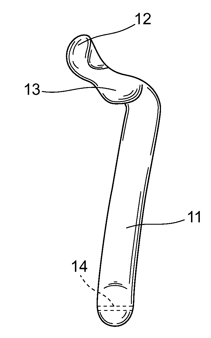
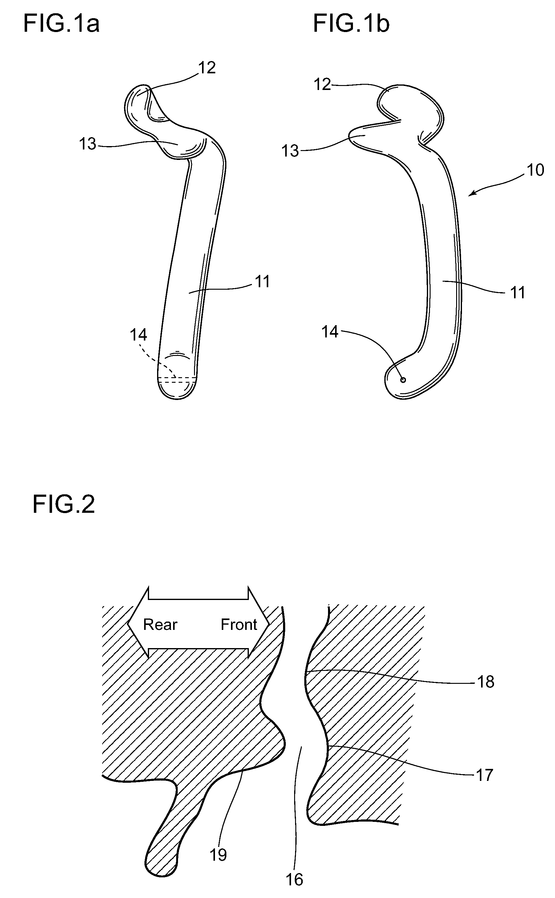
[0059]FIG. 1 is a front view (b) and a left side view (a) of a holder 10 illustrating Example 1 of the present invention. Two protrusions 12, 13 are provided at one end of a holding arm 11, and a hole 14 is provided at the other end, as shown in the front view (b). The holding arm 11 is a rod that has the overall shape of a bow when viewed from the side. Of the two protrusions 12, 13 provided to one end of the holding arm 11, the distal protrusion 12 is more easily inserted into the first curve of the external ear canal, and therefore has a slight spiral shape as shown in the left side view (a). The holder shown in FIG. 1 is used for the right ear and has a leftward spiraling shape, but a holder for the left ear would have a rightward spiraling shape.
[0060]Of the two protrusions 12, 13 provided to one end of the holding arm 11, the other protrusion, which is a restraining protrusion 13, rests in contact with the side surface of the cavity of concha, which is equivalent to the entran...
example 2
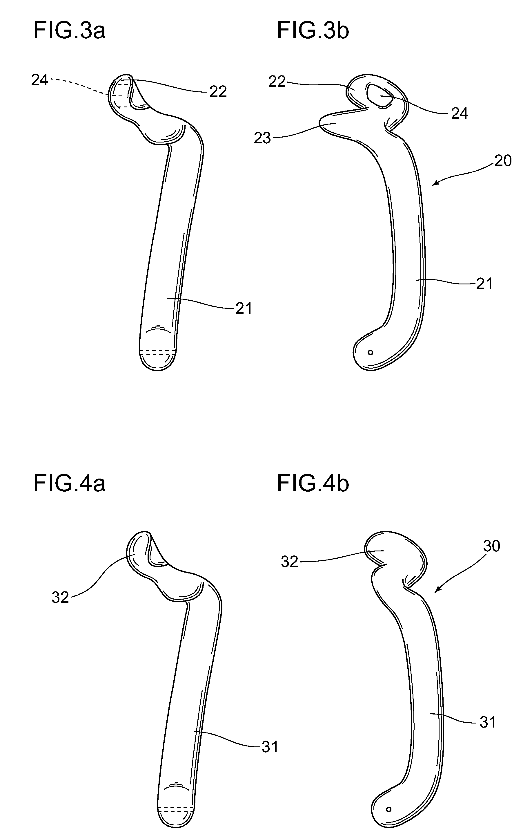
[0063]FIG. 3 is a front view (b) and left side view (a) of a holder 20 illustrating Example 2 of the present invention. The essential shape of the holding arm 21 in the present example is the same as that of the holding arm 11 shown in Example 1. The difference is that the shape of a distal protrusion 22 has a groove-shaped opening 24. The distal protrusion 22 is inserted up to the first curve 17 of the external ear canal 16 and is the most important part for attaching the holder 20 to the external ear canal 16. With the distal protrusion 12 shown in Example 1, however, the external ear canal 16 is closed off, inhibiting auditory perception of the surrounding environment. The distal protrusion 22 in the external ear canal 16 is at substantially a right angle to the external ear canal 16, as in the state shown in the front view (b) in FIG. 3. In view of this, a hole 24 is formed in the distal protrusion 22 as shown in the front view (b) in FIG. 3. Specifically, the distal protrusion ...
example 3
[0065]FIG. 4 is a front view (b) and left side view (a) of a holder 30 illustrating Example 3 of the present invention. The holding arm 31 in the present example also has essentially the same shape as the holding arms 11 and 21 of Examples 1 and 2. The significant difference is in the restraining protrusion. The restraining protrusions 13 and 23 in the holding arms 11 and 21 shown in Examples 1 and 2 constituted protrusions, as the name implied. In the present example, there is no portion equivalent to a restraining protrusion. The distal end 32 of the rod shape of the holding arm 31 bends to form an attachment and fulfills the role of a distal protrusion, and the distal end 32 of this attachment is inserted into the first curve 17 of the external ear canal to hold a load at the other end of the holding arm 31. Another possibility is to form an attachment wound in a spiral shape on the distal end 32 of the holding arm 31, in place of a bent attachment. The other end of the holding a...
PUM
 Abstract
Description
Claims
Application Information
 - R&D
- Intellectual Property
- Life Sciences
- Materials
- Tech Scout
- Unparalleled Data Quality
- Higher Quality Content
- 60% Fewer Hallucinations
Browse by: Latest US Patents, China's latest patents, Technical Efficacy Thesaurus, Application Domain, Technology Topic, Popular Technical Reports.
© 2025 PatSnap. All rights reserved.Legal|Privacy policy|Modern Slavery Act Transparency Statement|Sitemap|About US| Contact US: help@patsnap.com


