
Method and apparatus for positioning reinforcing members within hardened material structures

a technology for reinforcing members and hardening materials, applied in the direction of building reinforcements, paving reinforcements, construction, etc., can solve the problems of increasing shipping and supervision costs, erode reinforcing members, and single elevation positioning devices suffer, so as to eliminate or minimize the voids in the hardening material. , the effect of accurate and efficient positioning of reinforcing members

Inactive Publication Date: 2009-05-14
EDELL SHAPIRO & FINNAN
View PDF21 Cites 20 Cited by
  • Summary
  • Abstract
  • Description
  • Claims
  • Application Information

AI Technical Summary

Benefits of technology

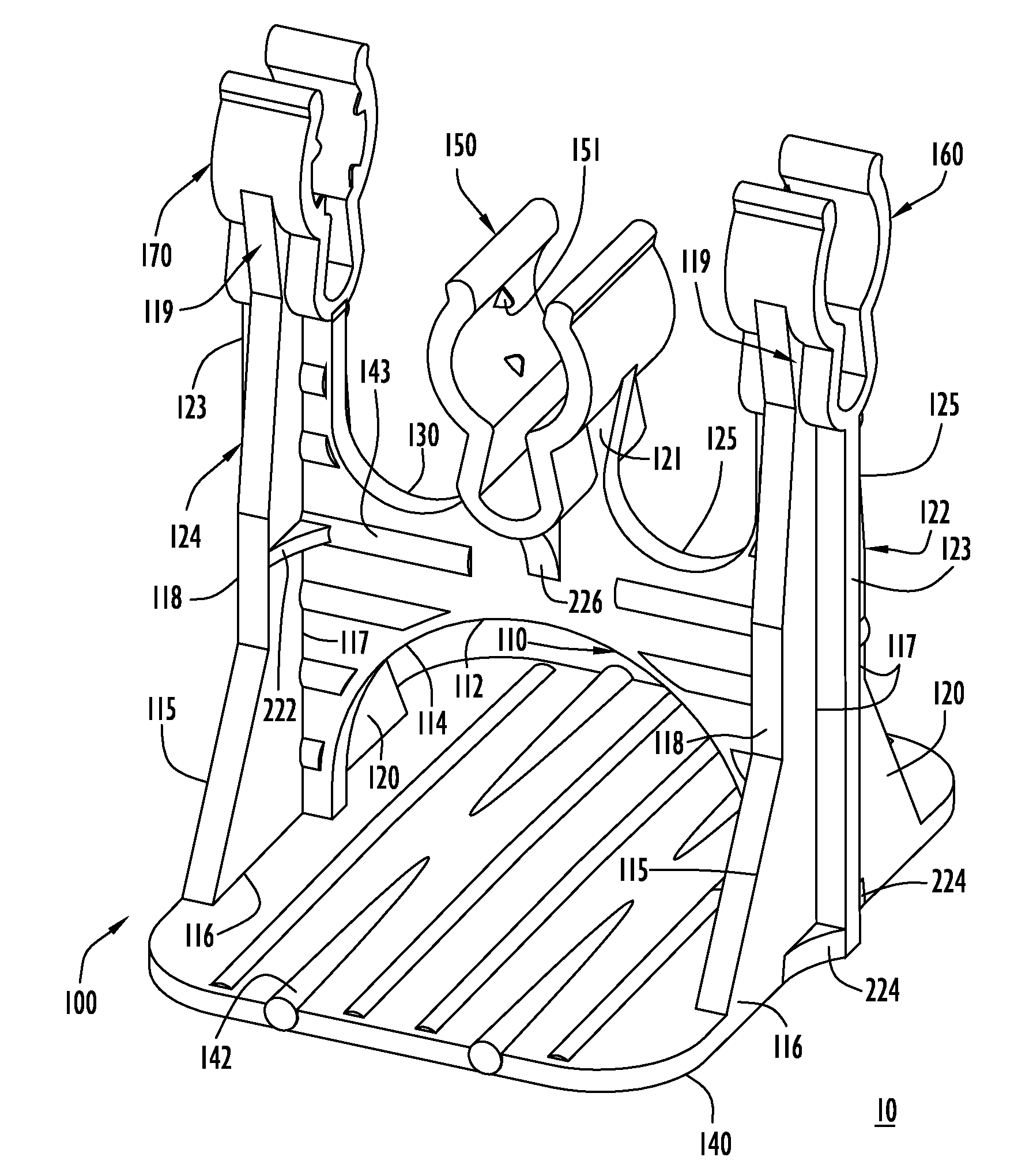
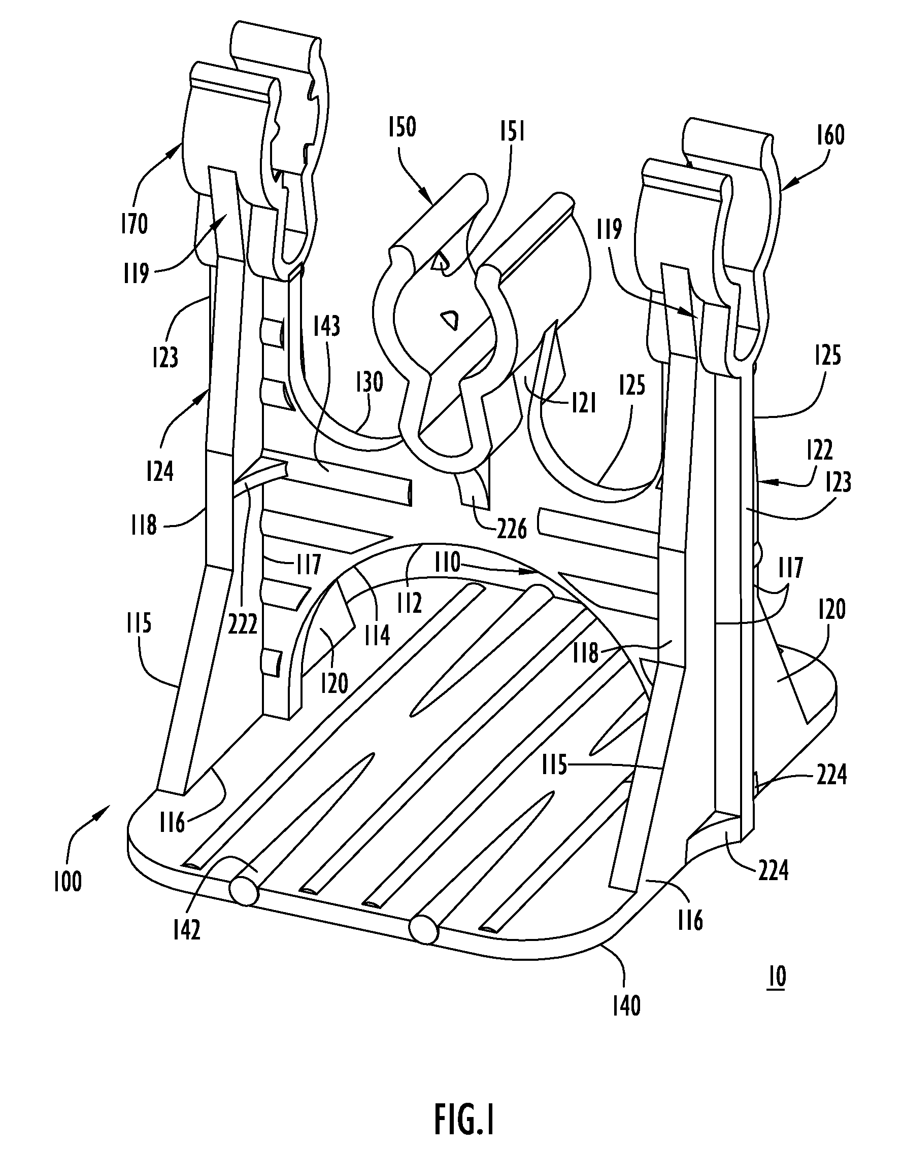
[0011]The present invention embodiments pertain to a support device for accurately and efficiently positioning reinforcing members (e.g., rebar) within a hardened material structure such as a concrete slab. In particular, the present invention embodiments provide a chair for supporting reinforcing members in predetermined positions while a design space is filled with hardening material (e.g., concrete) that hardens around the reinforcing members. The positioning device includes a base, a support member, and one or more receptacles or clips. The base contacts a support surface (e.g., a floor member on which hardening material is to be poured, etc.), while the support member is preferably H-shaped and formed generally by side members that connect to and extend from the base and a bridge member that extends between the side members. The connection of the support member to the base stably supports the support member with the base resting against the support surface. The support member further includes one or more openings appropriately sized for ensuring adequate through flow of hardening material (e.g., flow of concrete, etc.), thereby eliminating or at least minimizing voids in the hardening material caused by restricted flow. In addition, the openings allow concrete to flow through / around the support device and the rebar segments.
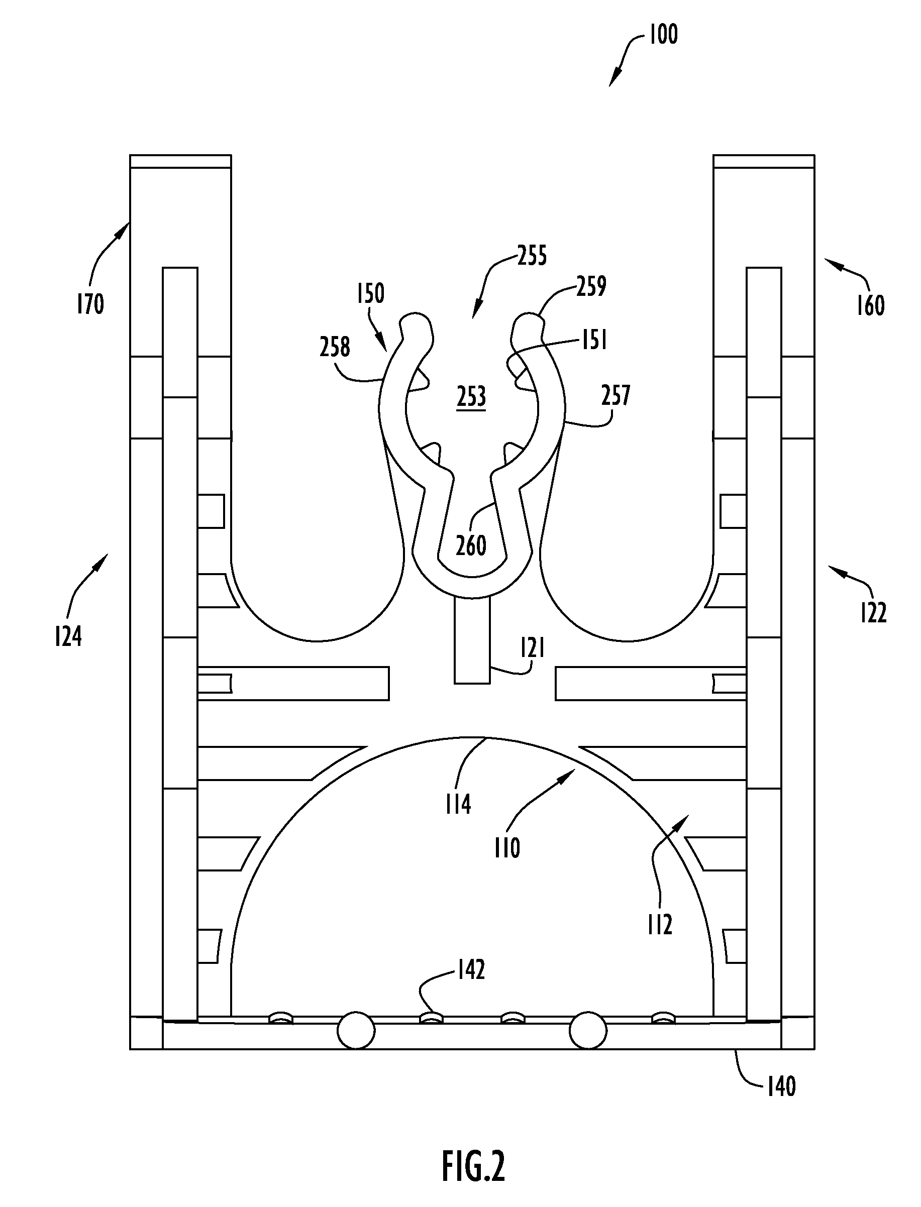
[0012]The distal end of the support member includes one or more receptacles or clips for receiving reinforcing members. Each clip includes curved arms that form a generally C-shape and define a holding area for receiving a corresponding reinforcing member therein. The arms are flexible and include an opening therebetween leading to the holding area. A proximal clip portion includes a plurality of branches that extend the arm length to increase flexibility. Reinforcing members force the arms apart during insertion, thereby enabling reinforcing members with slightly larger dimensions to be accommodated by the clip. The arms subsequently move toward their original position once the reinforcing member has passed through the opening into the clip holding area.
[0014]The support device may further include a series of stiffening members located in areas of the positioning device that experience elevated stresses. The stiffening members enable the positioning device to be created using minimal material without sacrificing strength, and facilitate employment of the flow opening in the support member since the stiffeners supplement the support member strength.
[0015]In addition, the positioning devices of the present invention embodiments include indicia for clearly indicating dimensions (e.g., the distance from the base to the clip, etc.) of the positioning device. This enables a user in the field to quickly and accurately identify units of the device that are appropriately sized for a specific use.

Problems solved by technology

Further, reinforcing members positioned close to the slab top surface may enable moisture to penetrate the slab and erode the reinforcing members.
These single elevation positioning devices suffer from several disadvantages.
First, they are specific to slab thicknesses, where a user maintains several different devices in order to accommodate those thicknesses, which increases shipping and supervision costs.
Second, this type of positioning device tends to be manufactured at low cost, thereby resulting in devices with inadequate strength due to a deficient design and / or being molded from a low quality material or thermoplastic.
Consequently, the devices fail in response to excessive loads, or deform from temperatures encountered during shipping or at a construction site.
Thus, user confidence levels for these devices are significantly reduced.
These types of devices tend to be heavier and more expensive (relative to the single elevation devices), and are confusing for a user to utilize.
Since a slab typically employs numerous positioning devices, the additional time to position the reinforcing member within the positioning device significantly increases costs.
Further, this arrangement complicates verification of proper installment of the positioning devices.
For example, a reinforcement member may be placed within an incorrect receptacle of a positioning device, thereby resulting in that member being positioned at an incorrect elevation or being supported improperly.
If the reinforcing member is placed within a slot with greater dimensions than those of the member, the slot provides poor support.
However, a slot of lesser dimensions relative to the reinforcing member provides improper seating and incorrect elevation.
In addition, the lesser dimensioned slot provides additional stresses that may damage the positioning device and facilitate poor support.
Finally, conventional support devices do not permit the flow of the hardening material and its aggregate completely around the support device, the rebar segments and / or the receptacles.
This introduces fracture points in an around the support device, weakening the resulting structural element.

Method used


Image

  • Method and apparatus for positioning reinforcing members within hardened material structures
  • Method and apparatus for positioning reinforcing members within hardened material structures
  • Method and apparatus for positioning reinforcing members within hardened material structures

Examples


Embodiment Construction

[0024]The present invention embodiments pertain to an effective, low cost and lightweight support device (or chair) configured to precisely position reinforcing members (e.g., rebar) in a hardened material (e.g., concrete, etc.) structure. A support device according to an embodiment of the present invention is illustrated in FIGS. 1-3. Specifically, support device 100 includes a base 140, a support member 110 supported by base 140, and a plurality of receptacles or clips 150, 160, 170 extending from support member 110 to receive reinforcing members as described below.

[0025]Base 140 contacts a support surface 10 and supports support member 110 in a steady manner during use. Typically, support surface 10 is an interior surface of a containment structure (e.g., the temporary support decking of a building floor slab, etc.) within which the hardening material is placed. In addition, base 140 may engage support surface 10 in any orientation (e.g., horizontally for supporting reinforcing m...


PUM

PropertyMeasurementUnit
Temperatureaaaaaaaaaa
Flow rateaaaaaaaaaa
Sizeaaaaaaaaaa

Abstract

A positioning device for accurately positioning a reinforcing member in a hardening material (e.g., concrete). The positioning device is made from a plastic material and includes a base and a support member extending from the base. The base includes at least one receiving member supported on the support member. The receiving member is in the form of a flexible clip or spring clip. The clips are C-shaped and include arms with an opening between the arms which leads to a holding area. Each clip is capable of receiving reinforcing members of varying sizes within the opening. The clips flex outward to accommodate a reinforcing member and subsequently return inward toward a rest mode to contact and secure the reinforcing member within the holding area. The clips may be positioned at various heights and orientations.

Description

CROSS REFERENCE TO RELATED APPLICATIONS[0001]This application claims priority to U.S. Provisional Patent Application No. 60 / 987,034, entitled “Intersecting Rebar and Tension Cable Support Chair” and filed 10 Nov. 2007, the disclosure of which is incorporated herein by reference in its entirety.BACKGROUND OF THE INVENTION[0002]1. Technical Field[0003]The present invention embodiments pertain to devices operable to support reinforcing members within concrete or other hardened material structures. In particular, the present invention embodiments pertain to positioning reinforcement members (e.g., rebar or tension cable, etc.) in an area receiving concrete or other hardening material to enable the reinforcing members to be located accurately subsequent to hardening of the material to provide sufficient reinforcement.[0004]2. Discussion of Related Art[0005]In reinforced concrete structural elements (such as slabs, columns, beams, walls, floors, etc.), concrete and reinforcing steel are c...

Claims


Application Information

Patent Timeline
IPC IPC(8): E04C5/20E01C11/18
CPCE04C5/20
Inventor GARZA, FRANCISCO L.
Owner EDELL SHAPIRO & FINNAN
Learn More