Bicycle torque measuring system

a torque measurement and bicycle technology, applied in the field of bicycle torque measurement system, can solve the problems of cycling not being able to evaluate individual leg performance, all being somewhat expensive,

Inactive Publication Date: 2009-05-14
MAGNUM ENG
View PDF15 Cites 98 Cited by
  • Summary
  • Abstract
  • Description
  • Claims
  • Application Information

AI Technical Summary

Benefits of technology

[0005]In the preferred embodiment of the invention, the main controller includes a microcontroller which is coupled to sensors to determine the instantaneous position of the individual crank arms. One sensor determines a reference position (such as top dead center for a pedal) and another sensor measures the sprocket position at several intervals. In one embodiment, t...

Problems solved by technology

These products are all somewhat costly and only display the total amount of power ge...

Method used


Image

  • Bicycle torque measuring system
  • Bicycle torque measuring system
  • Bicycle torque measuring system

Examples


Embodiment Construction

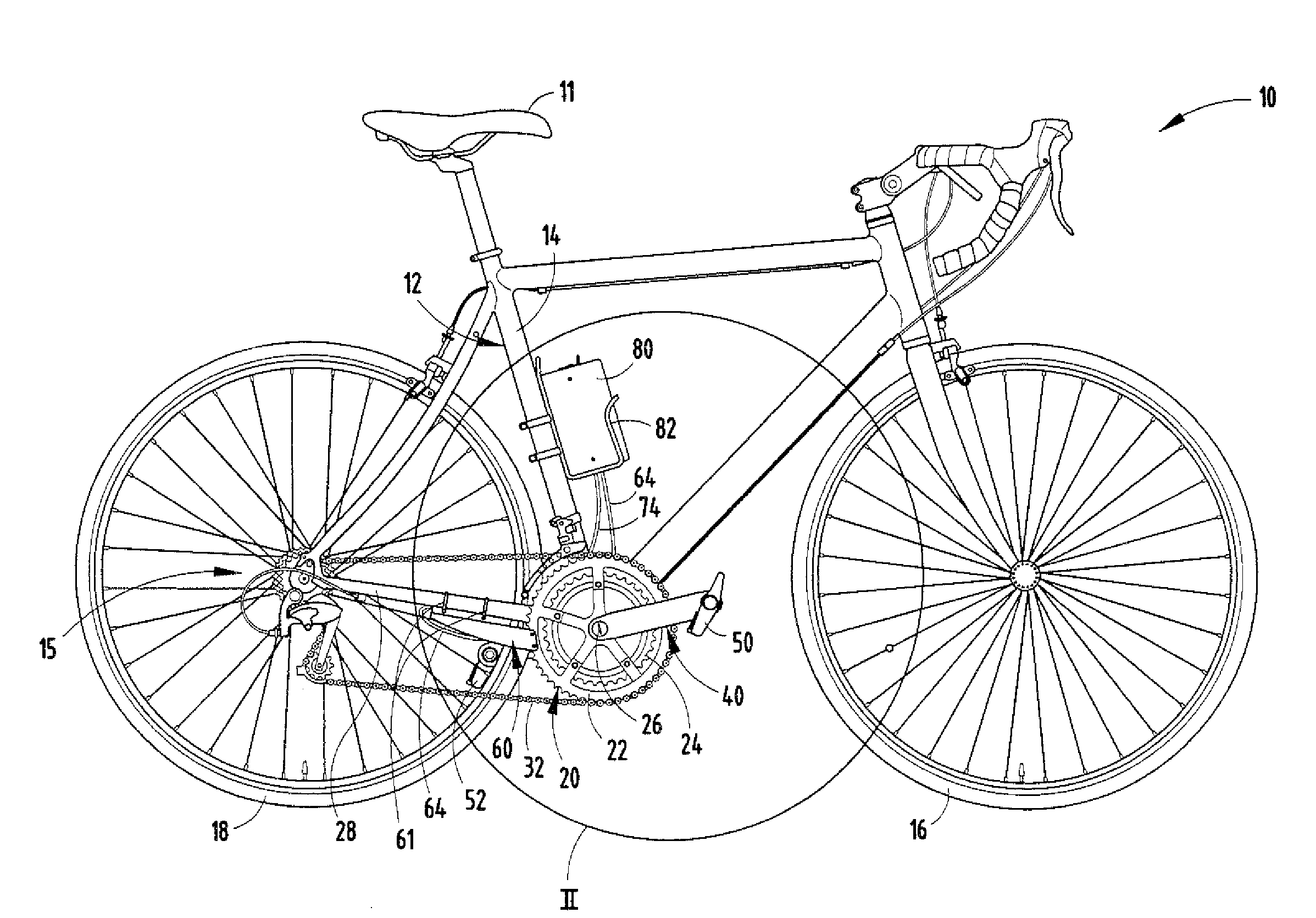
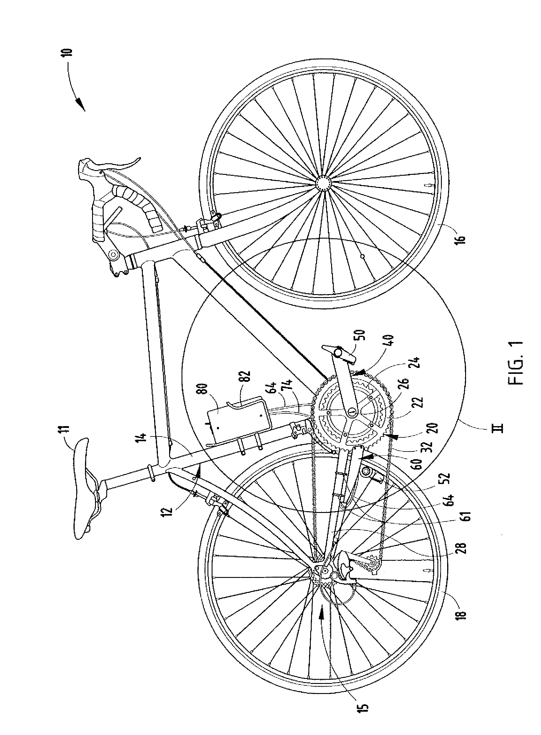
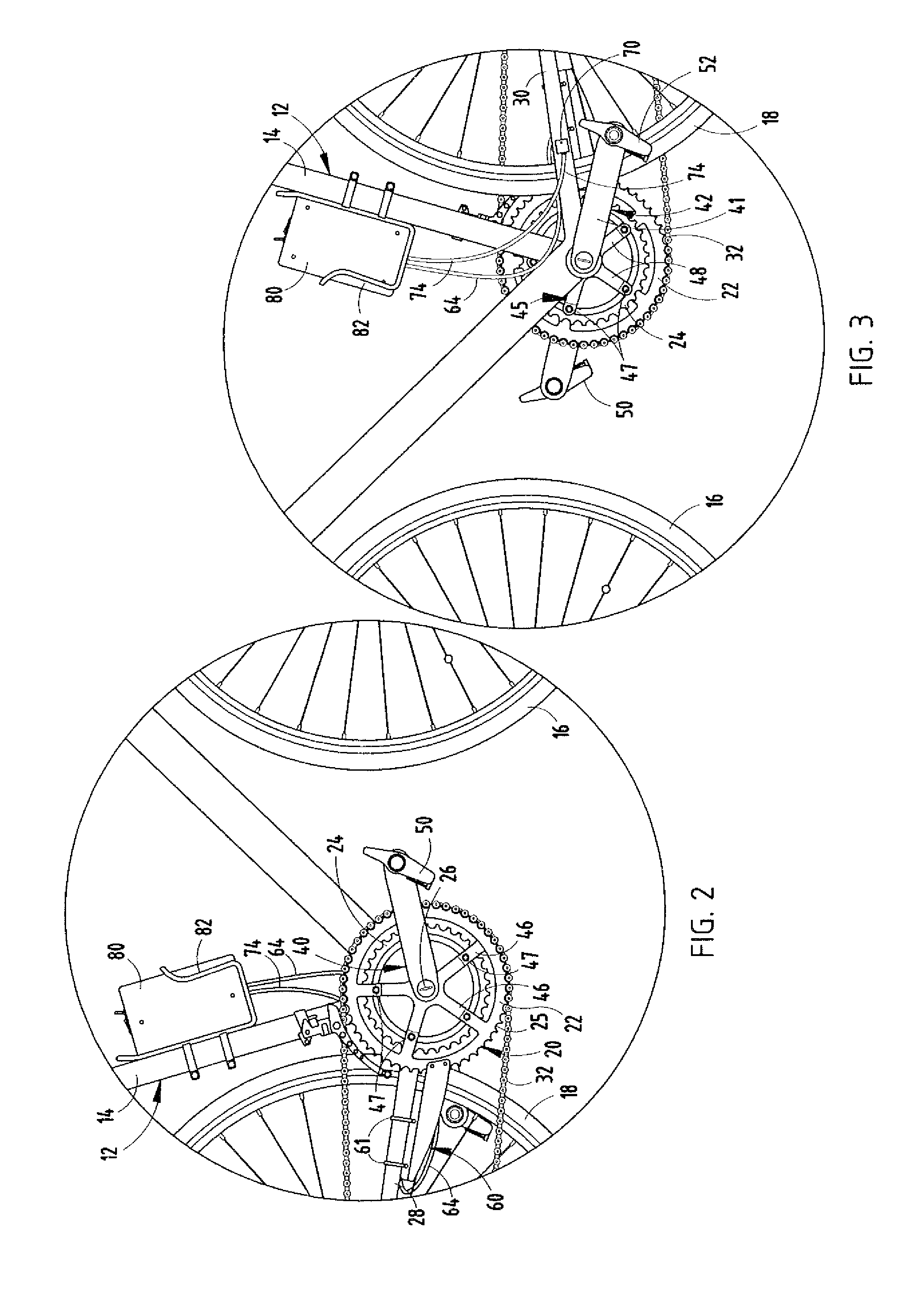
[0018]Referring initially to FIGS. 1-3, there is shown a bicycle 10 embodying the present invention. Bicycle 10 includes a racing frame 12 having a seat tube 14 supporting a seat 11, front wheel 16, a rear wheel 18, and a sprocket assembly 20, including an outer sprocket 22, an inner sprocket 24 with an axle 26 extending through the hub of frame 12 and keyed to sprockets 22 and 24. Frame 12 also includes a pair of horizontally and rearwardly extending frame members 28 and 30 which support a rear axle and derailer assembly 15 (FIG. 1) associated with the bicycle. The conventional crank arms associated with the sprockets, which drive chain 32, are replaced with crank arms 40 and 42 embodying the present invention. Crank arm 40 is mounted to sprockets 22 and 24 and to axle 26. Crank arm 40, which is shown in detail in FIGS. 4 and 5, includes a mounting spider 46 with five equally spaced legs 48 having apertures 49 for securing the spider to the aligned apertures of outer and inner spro...


PUM


Abstract

Strain gauges are mounted on each crank arm of the bicycle and provide a measure of the torque applied to each crank arm. In a preferred embodiment, strain gauges are mounted on opposite edges of each crank arm, which includes a self-contained power, electrical circuitry, and a wireless transmitter for transmitting the strain measurement information to a main controller. The main controller includes a wireless transceiver for transmitting and receiving data from both the left and right crank arms and external devices. Memory is also included for storing such data for subsequent analysis to determine the individual leg performance of a cyclist during a race or training session.

Description

BACKGROUND OF THE INVENTION[0001]The present invention relates to a system for measuring torque applied by each leg of the rider to the drive sprocket of a bicycle.[0002]Bicycle races have become an increasingly competitive sport where athletes involved train for several months and frequently are members of teams which compete professionally. Professional and other competitive racers employ a variety of training equipment to determine the total amount of power they deliver to the bicycle. There have been several proposals to record and allow the cyclist or trainer to analyze an individual cyclist's output power. The measurement methods employed include torque monitors mounted to the hubs of the bicycle to measure the power output to the wheels, strain gauges mounted within the sprocket spiders, chain tension measuring devices, and torsion sensors in the bottom bracket of the bicycle. These products are all somewhat costly and only display the total amount of power generated by the c...

Claims


Application Information

Patent Timeline
IPC IPC(8): G01L1/22B62M1/36
CPCG01L3/1457B62K2207/00B62M3/00G01L3/242B62J45/411B62J45/421
Inventor PHILLIPS, ROBERT RYANLINDELL, COTY W.MILLER, ADAM L.
Owner MAGNUM ENG
Why Eureka
Try Eureka