
Compliant coupling or adaptor

a technology of coupling or adaptor, which is applied in the direction of hose connection, cable termination, separation process, etc., can solve the problems of patient discomfort and dry airway of the patien

Active Publication Date: 2009-05-14
RESMED LTD
View PDF25 Cites 36 Cited by
  • Summary
  • Abstract
  • Description
  • Claims
  • Application Information

AI Technical Summary

Problems solved by technology

This can lead to drying of the patient's airway and patient discomfort.
Third, it is necessary to properly align and couple the humidifier tub and the flow generator.

Method used


Image

  • Compliant coupling or adaptor
  • Compliant coupling or adaptor
  • Compliant coupling or adaptor

Examples


Embodiment Construction

1. CPAP Device

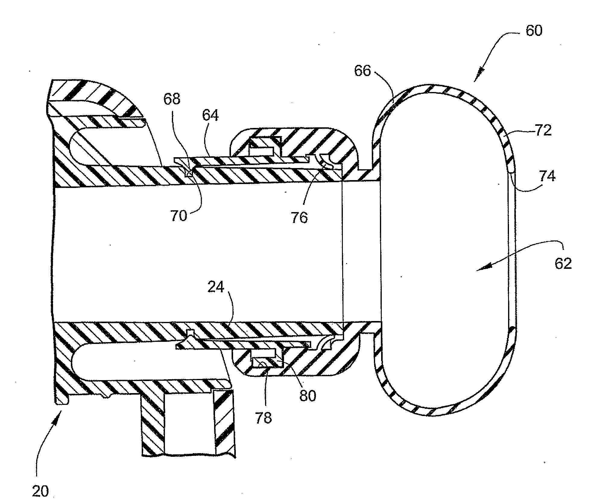
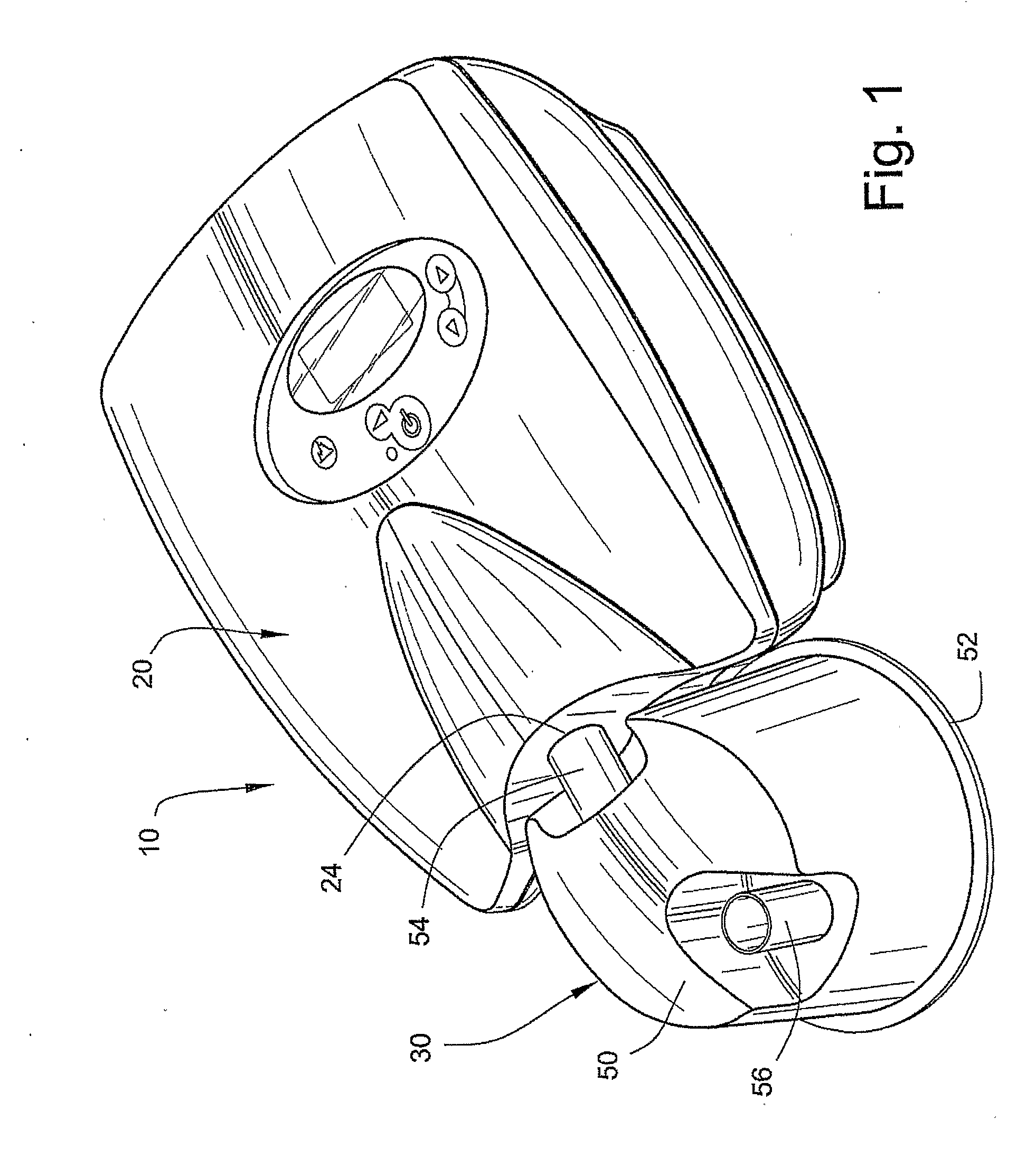
[0034]FIG. 1 illustrates a CPAP device 10 according to an embodiment of the present invention. As illustrated, the CPAP device 10 includes a flow generator 20 and a humidifier 30 adapted to be coupled to the flow generator 20. The humidifier 30 and the flow generator 20 may be mounted to or supported by a common support or cradle.

2. Humidifier

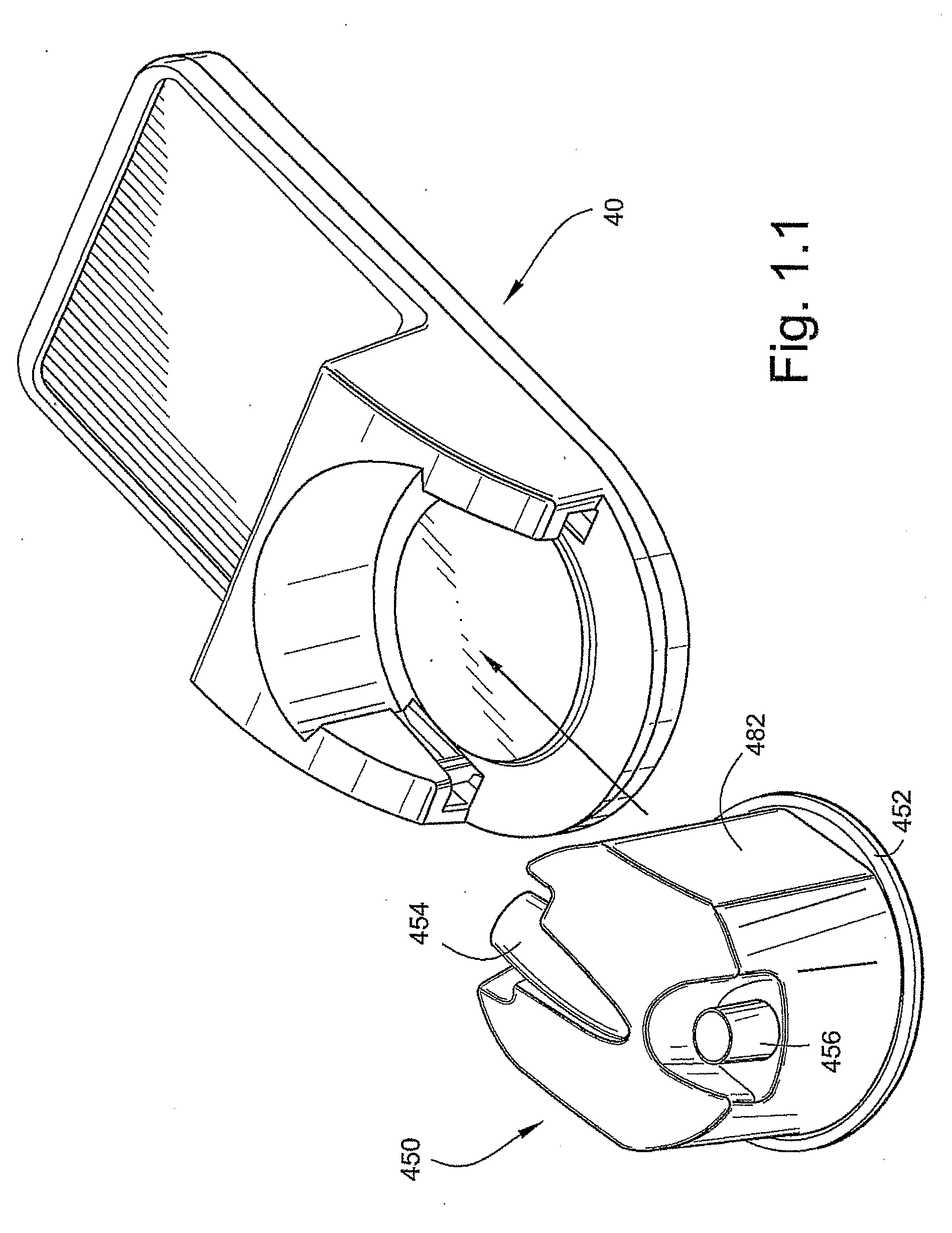
[0035]The humidifier 30 includes a humidifier tub 50 having a base plate 52 sealed to the bottom of the tub 50. The humidifier 30 includes or is otherwise associated with a heating element or plate that may be provided to a cradle 40 (FIG. 1.1). The cradle 40 includes a portion for supporting the flow generator. The tub 450 in FIG. 1.1 is slightly different from tub 50 in FIG. 1, e.g., tub 450 includes flattened sides 482 to facilitate alignment with cradle 40. The tub 50 includes an inlet 54 adapted to be in fluid communication with (i.e. not necessarily directly) the outlet 24 of the flow generator 20, and an outlet 56 adapted t...


PUM

PropertyMeasurementUnit
Lengthaaaaaaaaaa
Angleaaaaaaaaaa
Flexibilityaaaaaaaaaa

Abstract

A CPAP device includes a flow generator including an outlet, a humidifier including an inlet, and an adaptor connector between the outlet of the flow generator and the inlet of the humidifier. The connector includes a flexible and conformable sealing portion that is movable to accommodate misalignment.

Description

CROSS REFERENCE TO PRIORITY APPLICATION[0001]This application claims the benefit of U.S. Provisional Application No. 60 / 707,948, filed Aug. 15, 2005, incorporated herein by reference in its entirety.FIELD OF THE INVENTION[0002]The present invention relates to a compliant coupling or adaptor for use in communicating pressurized breathable gas between a blower or flow generator and a humidifier tub for a Continuous Positive Airway Pressure (CPAP) device used to treat sleep disordered breathing (SDB) conditions such as Obstructive Sleep Apnea (OSA).BACKGROUND OF THE INVENTION[0003]Domestic treatment of OSA and other SDB is usually done using a device that provides CPAP, e.g., nasal CPAP. A common configuration of a treatment system comprises a CPAP device and a patient interface, e.g., a nasal mask. The nasal mask forms a sealing interface with the patient's nasal passages in use so that the supply of air at positive pressure from the CPAP device may be delivered to the patient's airwa...

Claims


Application Information

Patent Timeline
IPC IPC(8): A61M16/08
CPCA61M16/0816A61M16/10A61M16/1075B01D47/02A61M2205/42A61M16/0075A61M16/109A61M16/16A61M16/0066A61M2205/21A61M2209/086A61M16/0616A61M16/0057A61M16/0666A61M16/08A61M16/0875A61M2205/02A61M2205/3334
Inventor SMITH, IAN MALCOLMSNOW, JOHN MICHAELLITHGOW, PERRY DAVIDKAO, DAN
Owner RESMED LTD
Learn More