
Medical device connector fitting

a technology for connecting devices and medical devices, applied in the field of medical line connector fittings, can solve the problems of difficult release and stuck connection between the medical line and the catheter hub

Inactive Publication Date: 2008-03-27
VENETEC INT INC
View PDF99 Cites 7 Cited by
  • Summary
  • Abstract
  • Description
  • Claims
  • Application Information

AI Technical Summary

Benefits of technology

[0020] The connector system can be used with an anchoring system. This combination provides a secure connection between the medical components and provides a secure anchor of the connection to the patient. The anchoring system includes a retainer which receives a least a portion of the connector fitting. The retainer has at least one receptacle (e.g., slot) that is adapted to receive the radially extending member on the connector fitting to inhibit longitudinal (i.e., axial) movement of the fitting relative to the retainer. In a preferred mode, the retainer includes a plurality of receptacles disposed longitudinally to offer multiple positions in which to position the connector fitting within the retainer. This affords the ability to coarsely align the connector fitting relative to the retainer before inserting the connector fitting into the retainer. The anchoring system also can include an anchor pad, which adheres to the patient's skin and on which the retainer is mounted.

Problems solved by technology

After use over an extended period of time, however, the luer connection between the medical line and the catheter hub may become stuck to each other and difficult to release.

Method used


Image

  • Medical device connector fitting
  • Medical device connector fitting
  • Medical device connector fitting

Examples


Embodiment Construction

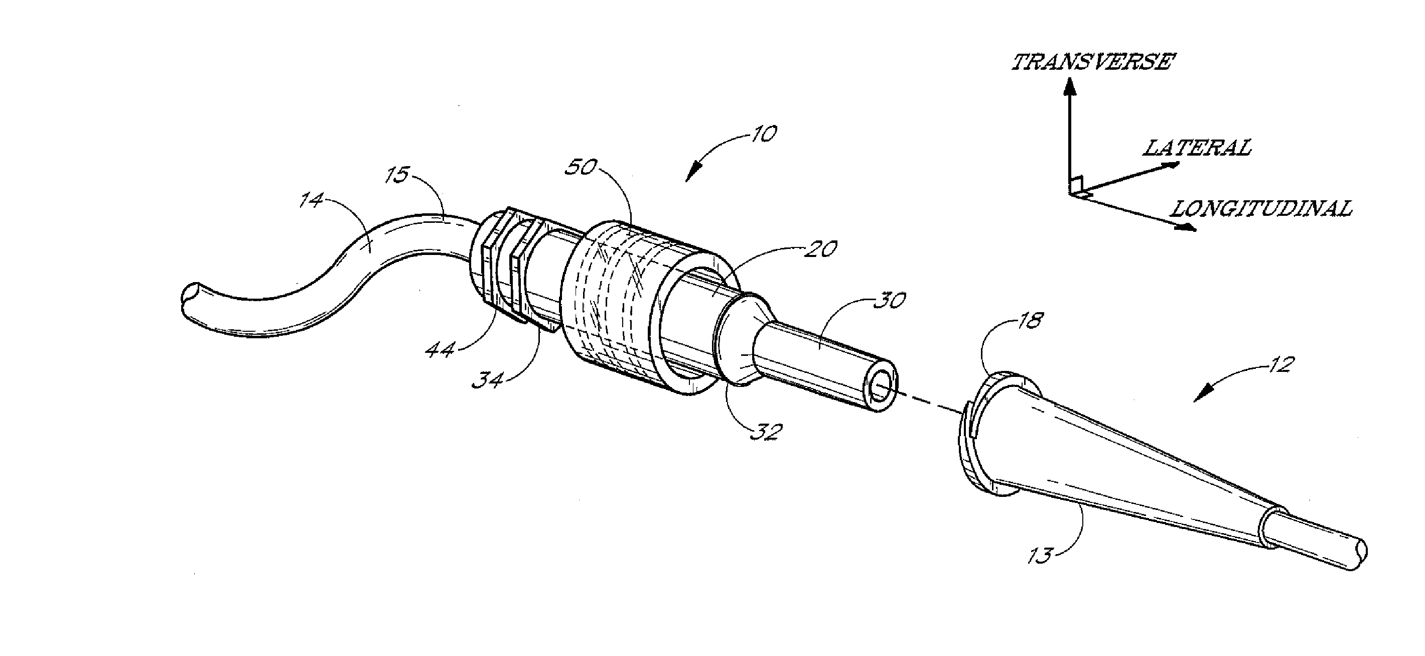
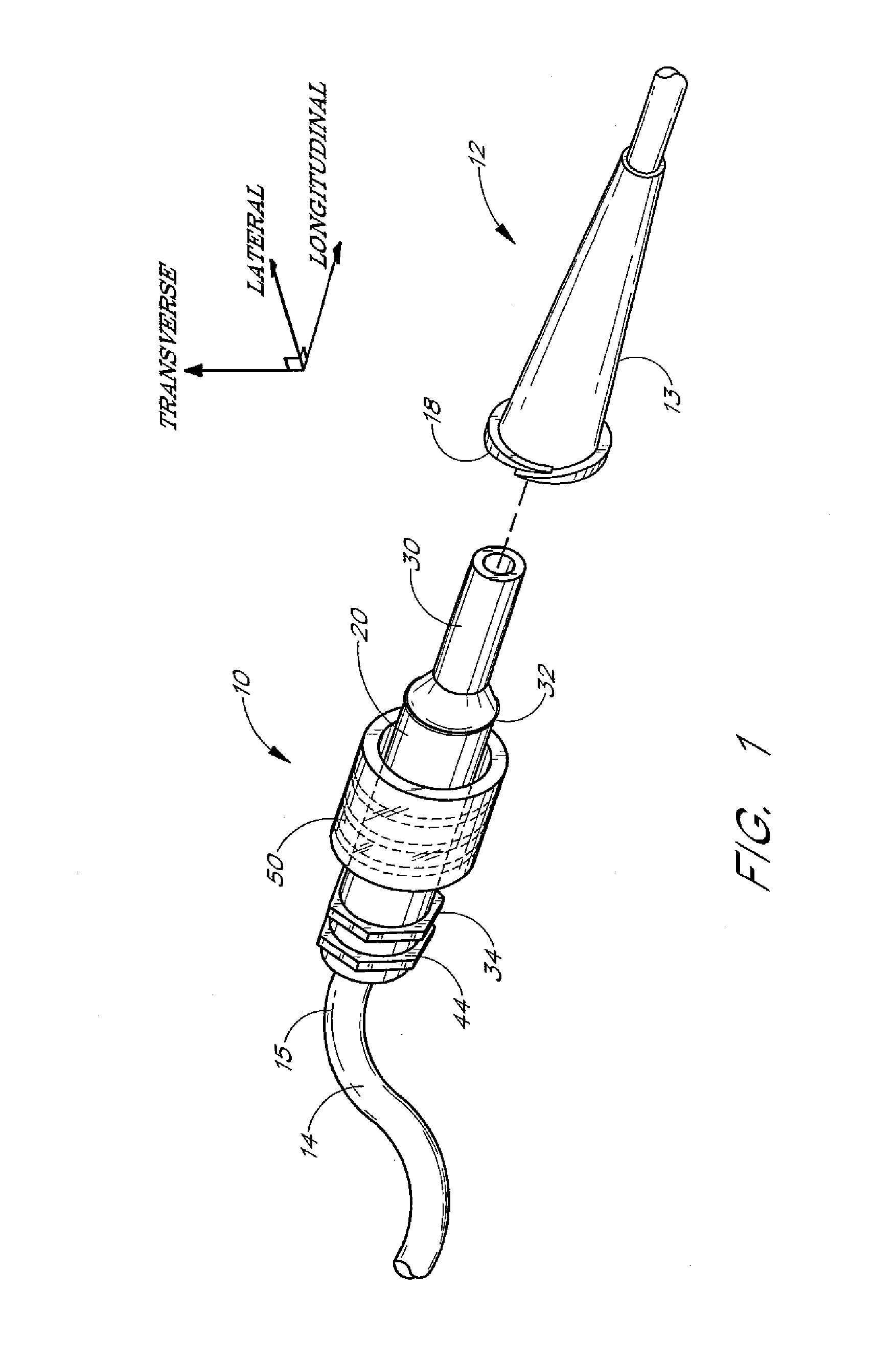
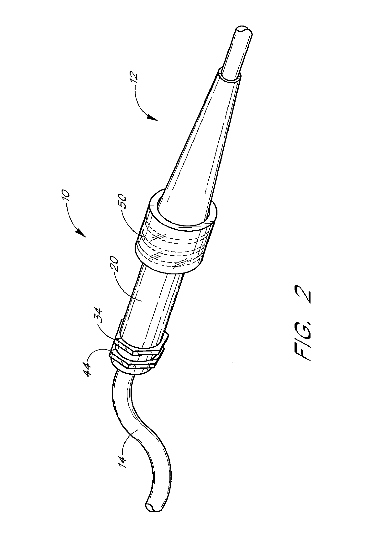
[0043] The following description and examples illustrate in detail a preferred embodiment of the present connector system disclosed in the context of use with an exemplary medical line and intravenous catheter. The principles of the present invention, however, are not limited to intravenous catheters. It will be understood by those of skill in the art in view of the present disclosure that the releasable connector system described may be applied to other types of medical articles, including without limitation, catheters and fluid delivery or drainage tubes. One skilled in the art may also find additional applications for the devices and systems disclosed herein. Thus the illustration and description of the connector system in connection with the medical line and catheter are merely exemplary of one possible application of the connector system.

[0044] To assist in the description of these components of the connector system (see FIG. 1), the following coordinate terms are used. A “lon...


PUM


Abstract

A releasable medical device connector comprises a connector fitting with a spin nut which connects to an adaptor. The connector fitting has at least one radially extending member with a variable radius cross section. The spin nut is disposed upon the connector fitting proximal of the radially extending member and is both axially slidable and rotatable upon the elongated body of the connector fitting. A screw thread within a proximal portion of the spin nut is used to secure the tapering portion of the connector fitting to an external thread disposed upon the adaptor. To release the connector, the spin nut is unscrewed from the adaptor and slid so that a distal receptacle of the spin nut engages the radially extending member of the connector fitting. With the spin nut and connector fitting engaged, the medical line can be released from the adaptor by twisting and pulling upon the spin nut. The radially extending member of the connector fitting may also be used to secure the medical line to a retainer comprising one or more slots.

Description

RELATED APPLICATIONS [0001] This application is a divisional of U.S. application patent Ser. No. 09 / 767,207, filed Jan. 22, 2001, and entitled MEDICAL DEVICE CONNECTOR FITTING, which is hereby expressly incorporated by reference in its entirety.BACKGROUND OF THE INVENTION [0002] 1. Field of the Invention [0003] The present invention relates in general to a medical line connector fitting, and more specifically, to a releasable connector for use on an elongated medical article. [0004] 2. Description of Related Art [0005] It is frequently desirable in the medical treatment of patients for medical personnel to have some form of access to the vasculature of the patient for delivery or withdrawal of fluids from the bloodstream. When such access is required over any period of time, it is common to introduce a catheter into the bloodstream of the patient to provide reusable access, for instance in order to deliver medication and / or fluids directly into the bloodstream of the patient. It may...

Claims


Application Information

Patent Timeline
Patent Type & Authority Applications(United States)
IPC IPC(8): A61M25/18A61M1/14A61M25/02A61M39/02A61M39/00A61M39/10
CPCA61M25/02A61M39/10Y10S128/26A61M2039/1077A61M2039/1033
Inventor BIERMAN, STEVEN F.
Owner VENETEC INT INC
Learn More