Pipe laser

a laser and pipe technology, applied in the field of construction, can solve the problems of compromising affecting the integrity of the building, and consuming a lot of time, and the limitations of manual measurement and oversized drilling of holes have not yet been overcom

Inactive Publication Date: 2021-06-24
LINDBERG RYAN SCOTT
View PDF19 Cites 6 Cited by
  • Summary
  • Abstract
  • Description
  • Claims
  • Application Information

AI Technical Summary

Benefits of technology

[0006]The pipe laser has an adaptor/connector that can fit inside an existing plumbing pipe to attach the pipe laser device to the existing pipe. The device also has a laser diode within the device that delivers the laser beam from the opposite end of the device. The laser diode is centered on the connector that sits within the existing pipe, and so allows the laser beam delivered from the other end to als

Problems solved by technology

When installing plumbing during construction or other similar construction related work, there are various challenges involved in achieving accuracy in the installation.
Manual measurement is very time consuming and is not entirely accurate.
However, this can compromise the integrity of the building.
These limitations associated with manual measurement and oversized drilling of holes have not yet been overcome.
However, these solutions are still limited since neithe

Method used


Image

  • Pipe laser
  • Pipe laser
  • Pipe laser

Examples


Embodiment Construction

I. Pipe Laser Device

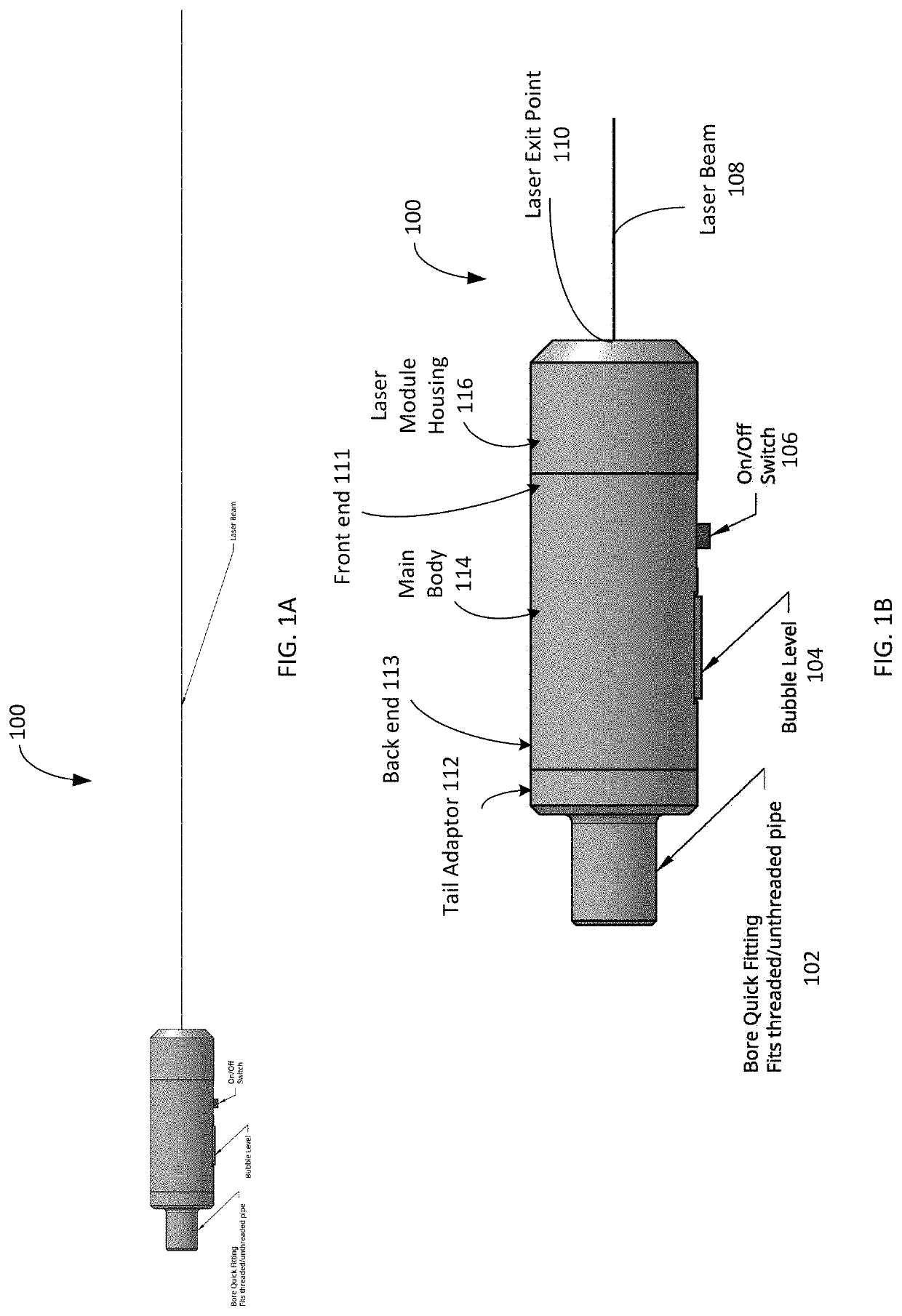
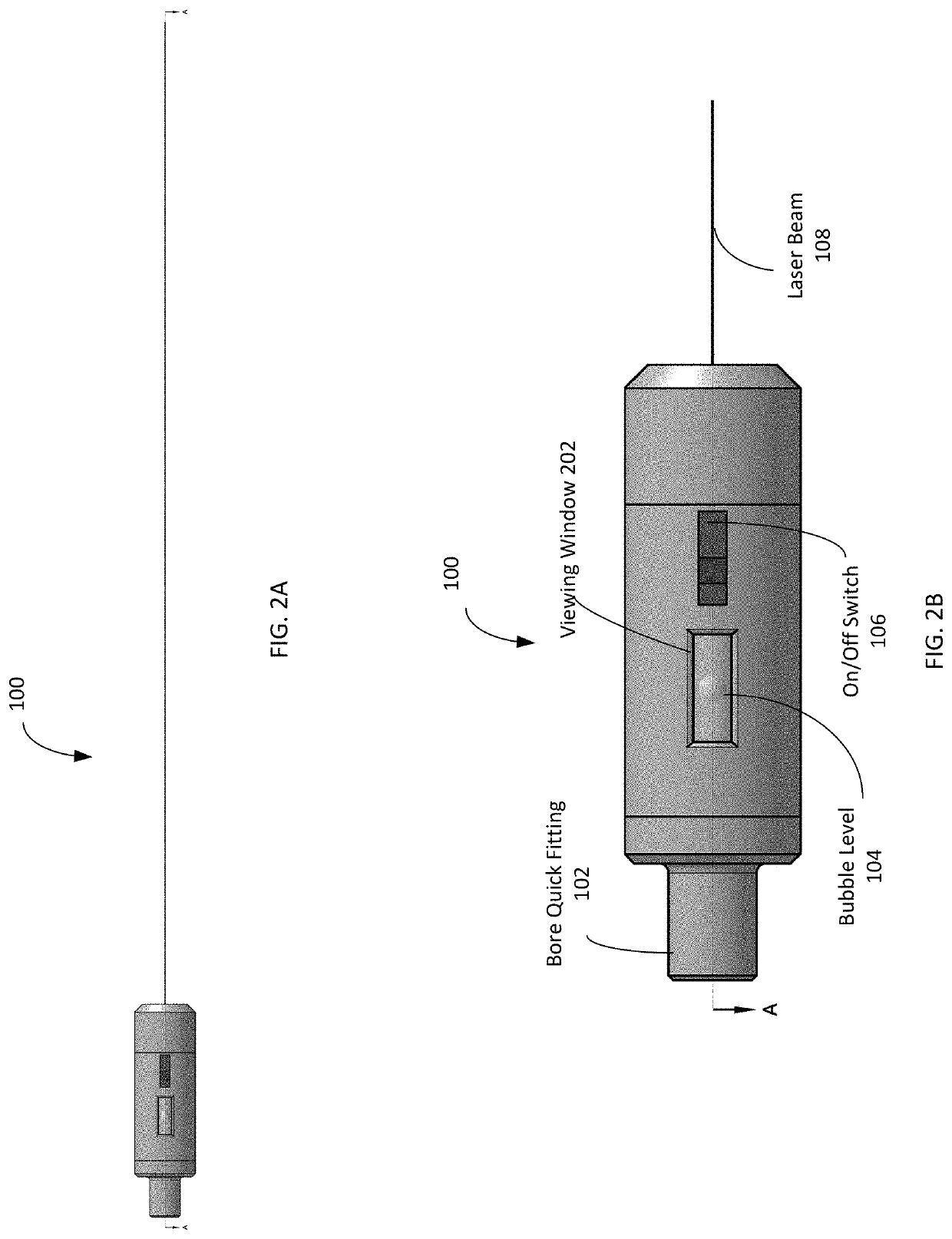
[0026]FIGS. 1A and 1B are side views of a piper laser device 100, with FIG. 1B being a magnified view of the device 100 in FIG. 1A according to embodiments of the invention. The pipe laser 100 includes three main sections, the tail adaptor (or plumbing connector) section 112, the main body 114 and the laser module housing 116. In this and other figures, there are multiple components shown, but in each figure, the components can be exchanged for other different components or not included, according to various embodiments. Similarly, additional components can be added that are not show in each of the figures. The term “pipe laser” is used throughout to refer to examples, but this term encompasses other designs for emitting any type of beam, including those that are not a laser.

[0027]The pipe laser 100 is attachable to plumbing via the tail adaptor 112. This tail adaptor 112 section can be removable such that different adaptors can be attached to the tail end of the...


PUM


Abstract

A pipe laser device is attached to plumbing that will be added to or extended to show the angle and direction of where the existing plumbing is pointing so the installer knows precisely where to drill to accommodate the new plumbing. The pipe laser has an adaptor/connector that can fit inside an existing plumbing pipe to attach the pipe laser device to the existing pipe. The device has an emitter (laser diode) within the device that delivers the beam (laser beam) from the opposite end of the device. The laser diode is centered on connector that sits within the existing pipe, and so allows the laser beam delivered from the other end to also be centered relative to the existing pipe. Thus, the beam from the opposite end can precisely indicate where on an opposing wall the opening should be created for the existing plumbing to continue through that wall.

Description

CROSS REFERENCE TO RELATED APPLICATIONS[0001]This application claims priority to U.S. Provisional Application No. 62 / 952,046, filed on Dec. 20, 2019, which is incorporated by reference in its entirety for all purposes.BACKGROUND1. Field of Invention[0002]This invention relates generally to the field of construction, and particularly to a solution for plumbing installation.2. Description of the Related Art[0003]When installing plumbing during construction or other similar construction related work, there are various challenges involved in achieving accuracy in the installation. Commonly, professionals in this industry are required to perform manual measurements at the construction site, including using a pencil and tape measure. Manual measurement is very time consuming and is not entirely accurate. In addition, drilling oversized holes to accommodate the plumbing material is common. In current construction using manual measurement, the holes are drilled larger than is necessary to a...

Claims


Application Information

Patent Timeline
IPC IPC(8): G01C15/10G01C15/00
CPCG01C15/105G01C15/004
Inventor LINDBERG, RYAN SCOTT
Owner LINDBERG RYAN SCOTT
Why Eureka
Try Eureka