Pin component for optical fiber adaptor connector

A transfer connector and ferrule technology, which is applied in the field of ferrule components for optical fiber transfer connectors, can solve the problems of increased production cycle, low pass rate, and low production efficiency, and achieve simple manufacturing process, shortened production cycle, and qualified high rate effect

Active Publication Date: 2012-10-17
CHINA AVIATION OPTICAL-ELECTRICAL TECH CO LTD
View PDF4 Cites 7 Cited by
  • Summary
  • Abstract
  • Description
  • Claims
  • Application Information

AI Technical Summary

Problems solved by technology

[0002] Because the optical fiber transfer connector needs to transfer the optical path, it needs both ends to be mated with the matching connector at the same time during use. In some occasions, the transfer connector is required to pass through the wall, that is, its two ends are respectively located Inside and outside the body, this requires the length of the internal transfer contact to be longer. In the prior art, the transfer contact of most optical fiber transfer connectors is a single ceramic ferrule. Since the ceramic ferrule is Slender structure, so the processing and assembly process of the product is extremely complicated, and the product qualification rate is low, thus increasing the production cycle and low production efficiency
Of course, there is also a form of using standard LC ferrule parts and using molded non-metal to buckle and then make an adapter ferrule

Method used


Image

  • Pin component for optical fiber adaptor connector
  • Pin component for optical fiber adaptor connector
  • Pin component for optical fiber adaptor connector

Examples


Embodiment Construction

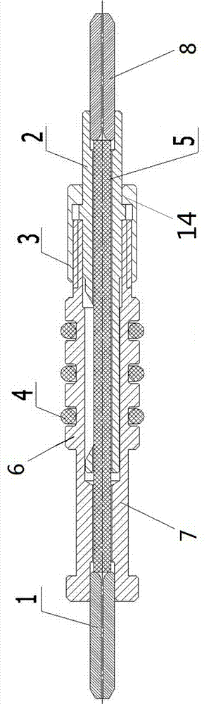
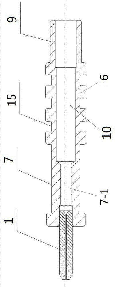
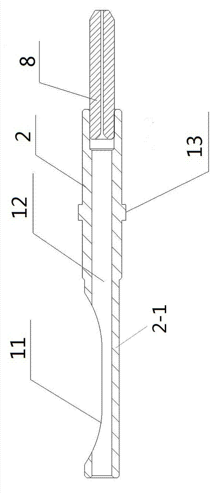
[0018] Examples of ferrule assemblies for fiber optic transition connectors are Figure 1~3 Shown: including the sheath 6 and the front flange 7 and the rear flange 2 respectively assembled at the front and rear ends of the sheath 6, the front flange 7 and the sheath 6 are integrated, the rear flange 2 and the sheath Split settings. The pin assembly also includes a front pin 1 and a rear pin 8 respectively crimped and fixedly connected to the front and rear flanges, and an optical cable 5 connecting the two ceramic pins. The rear flange 2 is provided with an optical cable installation hole 12 connected to the front end of the rear pin 8, the rear end of the optical cable 5 is fixed in the optical cable installation hole 12, and the optical cable 5 is inserted into the sheath 6 after the flange 2 In the hole 10, the pin assembly also includes a fixed connection structure for connecting and fixing the sheath 6 and the rear flange 2 after the optical cable 5 and the flange 2 are...


PUM


Abstract

The invention relates to a pin component for an optical fiber adaptor connector. The pin component comprises a sheath, a front flange plate, a rear flange plate, a front pin, a rear pin, an optical cable and a fixing connection structure, wherein the front flange plate and the rear flange plate are respectively arranged at the front and rear ends of the sheath; the front pin and the rear pin are respectively assembled in the front flange plate and the rear flange plate; the optical cable is connected with the two pins; the rear flange plate and the sheath are arranged in a split mode; an optical cable installation hole which is connected with the front end of the rear pin is formed in the rear flange plate; the optical cable is arranged in the optical cable installation hole; the optical cable is inserted into an inner hole of the sheath along with the rear flange plate; and the fixing connection structure is used for connecting and fixing the rear flange plate and the sheath after the optical cable is inserted into a flange plate installation hole along with the rear flange plate. The pin component for the optical fiber adaptor connector provided by the invention is easy to manufacture and high in production efficiency.

Description

technical field [0001] The invention relates to the field of optical fiber connectors, in particular to a ferrule assembly for an optical fiber transfer connector. Background technique [0002] Because the optical fiber transfer connector needs to transfer the optical path, it needs both ends to be mated with the matching connector at the same time during use. In some occasions, the transfer connector is required to pass through the wall, that is, its two ends are respectively located Inside and outside the body, this requires the length of the internal transfer contact to be longer. In the prior art, the transfer contact of most optical fiber transfer connectors is a single ceramic ferrule. Since the ceramic ferrule is Slender structure, so the processing and assembly process of the product is extremely complicated, and the product qualification rate is low, thereby increasing the production cycle and low production efficiency. Of course, there is also a form of using stan...

Claims


Application Information

Patent Timeline
IPC IPC(8): G02B6/38G02B6/36
Inventor 姚强
Owner CHINA AVIATION OPTICAL-ELECTRICAL TECH CO LTD
Why Eureka
Try Eureka