
Multiflavor beverage dispensing nozzle and dispenser using same

Inactive Publication Date: 2009-05-14
PENTAIR FLOW SERVICES
View PDF71 Cites 50 Cited by
  • Summary
  • Abstract
  • Description
  • Claims
  • Application Information

AI Technical Summary

Benefits of technology

[0011]An improved multiflavor beverage dispenser has been invented. In one embodiment, four different flavors of beverages can be dispensed from the same nozzle. With the preferred embodiment of the invention, the syrup and water are combined in an aesthetically pleasing manner, and cross-flavor contamination between dispensing of different beverages is prevented.
[0016]With the preferred embodiment of the invention, one nozzle can be used to dispense up to four different flavors, which allows for a wide variety of beverages to be dispensed with a dispenser having a small footprint. At the same time, the nozzle dispenses a beverage with a pleasing presentation, which is well mixed as it falls into the cup, and the syrup does not stay in the end of the syrup passageway where it would otherwise likely be dislodged when the next drink is dispensed, causing flavor carry-over.

Problems solved by technology

Accommodating a large number of mixing nozzles on a dispenser increases the size, and hence the “footprint” of the dispenser.
One common problem with a multiflavor nozzle is the carry-over mixing of flavors from one drink to the next.
Another problem that can occur with any mixing nozzle is incomplete mixing of the syrup and water.
The lack of complete mixing is a greater potential problem in a multiflavor nozzle because the design of the nozzle must accommodate several different syrup supply points within the nozzle.
Again, this effort is complicated in a multiflavor nozzle, where the syrup is introduced from different supply points in the nozzle.

Method used


Image

  • Multiflavor beverage dispensing nozzle and dispenser using same
  • Multiflavor beverage dispensing nozzle and dispenser using same
  • Multiflavor beverage dispensing nozzle and dispenser using same

Examples


Embodiment Construction

[0039]The present invention will now be further described. In the following passages, different aspects of the invention are defined in more detail. Each aspect so defined may be combined with any other aspect or aspects unless clearly indicated to the contrary. In particular, any feature indicated as being preferred or advantageous may be combined with any other feature or features indicated as being preferred or advantageous.

[0040]The term “sheet” used in the specification and claims has a meaning defined as follows. The term “sheet” designates a form of water flow that has a small thickness dimension and a substantially longer other dimension. The sheet need not be, and is typically not, flat. Rather, the sheet form of water flow will typically be hollow cylinder, with a conical component as the sheet form collapses into a solid stream.

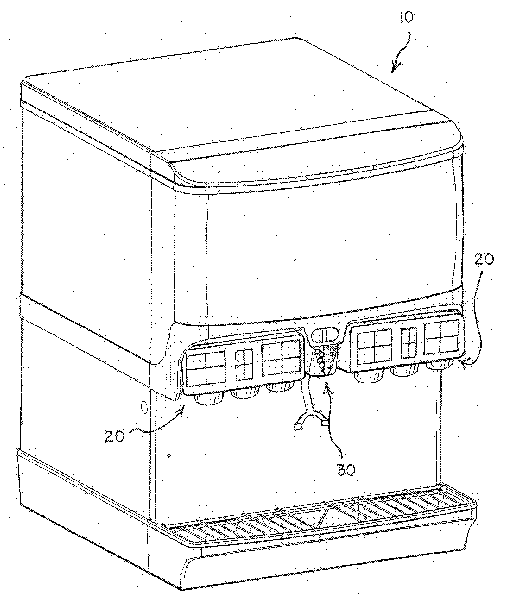
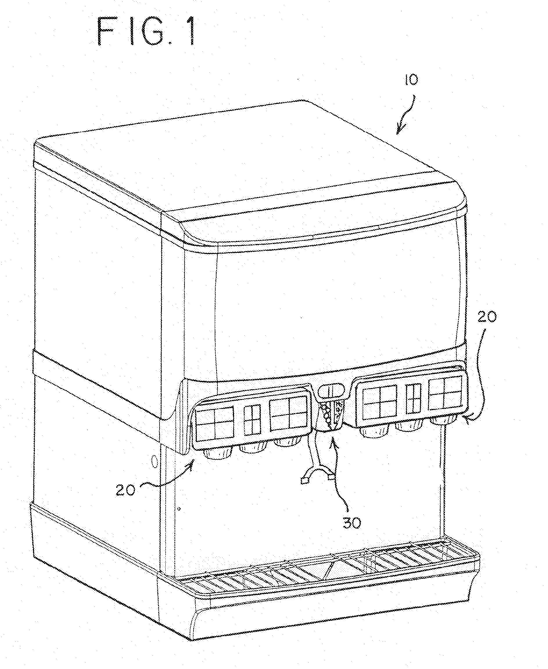
[0041]FIG. 1 depicts an embodiment of a combined ice and beverage dispenser 10 of the present invention. The dispenser 10 has six beverage dispens...


PUM


Abstract

A multiflavor beverage dispensing nozzle includes at least one water inlet; at least two syrup inlets; a main water flow path through the nozzle; and at least two syrup flow paths through the nozzle, one in fluid communication with each syrup inlet, each terminating in a syrup discharge port. In one aspect the water flow path is shaped to cause the water to discharge from the nozzle in a sheet form, preferably in an annular shape, and the syrup discharge ports include a syrup deflector shaped to cause the syrup to fan out as it exits the discharge port so that it impinges on the sheet of water. In another aspect the nozzle includes at least two secondary water flow paths that each divert water from the main flow path and discharge the diverted water through the at least two syrup discharge ports. A beverage dispenser utilizes a plurality of the multiflavor beverage dispensing nozzles incorporating one or both of the forgoing aspects. Optionally the dispenser also includes one or more dispensing nozzles for dispensing a favor additive, and may be equipped to dispense ice and even have an ice crusher so that it can dispense crushed or cubed ice.

Description

REFERENCE TO EARLIER FILED APPLICATIONS[0001]The present application claims the benefit of the filing date under 35 U.S.C. §119(e) of Provisional U.S. patent Application Ser. No. 60 / 985,914; which is hereby incorporated by reference in its entirety.BACKGROUND OF THE INVENTION[0002]The present invention relates to beverage dispensers and multiflavor dispensing nozzles used thereon.[0003]Beverage dispensers commonly mix a flavored concentrate with water to produce and dispense a beverage into a cup or other container for immediate consumption. Such dispensers are common in foodservice environments, such as fast-food restaurants and cafeterias. The water may be carbonated or non-carbonated, and many beverage dispensers are designed to be able to dispense both carbonated and non-carbonated beverages. Some beverage dispensers also dispense ice.[0004]Consumers appreciate having a wide selection of beverages to choose from. Thus most beverage dispensers are designed to mix different flavor...

Claims


Application Information

Patent Timeline
IPC IPC(8): B67D5/56B67D7/74
CPCB67D1/0052B67D1/0051
Inventor LANDERS, JERRY L.THOMPSON, GREGORY K.
Owner PENTAIR FLOW SERVICES
Features
  • Generate Ideas
  • Intellectual Property
  • Life Sciences
  • Materials
  • Tech Scout
  • Unparalleled Data Quality
  • Higher Quality Content
  • 60% Fewer Hallucinations
Learn More