Image Display Apparatus, Image Display Monitor, and Television Receiver

a technology of image display and monitor, which is applied in the field of image display equipment, can solve the problems of user eyestrain, apparatuses with high luminance and large screens, and the likelihood of flicker, etc., and achieve the effect of suppressing flicker, suppressing flicker, and suppressing the effect of moving image blurring

Inactive Publication Date: 2009-05-14
SHARP KK
View PDF61 Cites 38 Cited by
  • Summary
  • Abstract
  • Description
  • Claims
  • Application Information

AI Technical Summary

Benefits of technology

[0018]With this arrangement, in order to suppress blurring of a moving image, a display image signal can be generated by time-division driving, which is highly effective in suppressing blurring of a moving image (display in the first display mode). In order to suppress flickers, a display image signal can be generated by hold driving, in which flickers are less likely to occur (display in the second display mode). This makes it possible to effectively obtain the effect of suppressing blurring of a moving image by pseudo-impulse driving and to alleviate the problem of flickers caused by pseudo-impulse driving.

Problems solved by technology

However, when a display apparatus including a hold-type display element performs the above-mentioned pseudo-impulse driving for enhancement of moving image display performance, flickers are likely to occur.
This problem is also associated with recent trend toward display apparatuses with high luminance and large-sized screen.
Noticeable flickers occur particularly in case where a frame frequency is low, luminance is high, or other cases, and cause eyestrain in user's eyes.

Method used


Image

  • Image Display Apparatus, Image Display Monitor, and Television Receiver
  • Image Display Apparatus, Image Display Monitor, and Television Receiver
  • Image Display Apparatus, Image Display Monitor, and Television Receiver

Examples


first embodiment

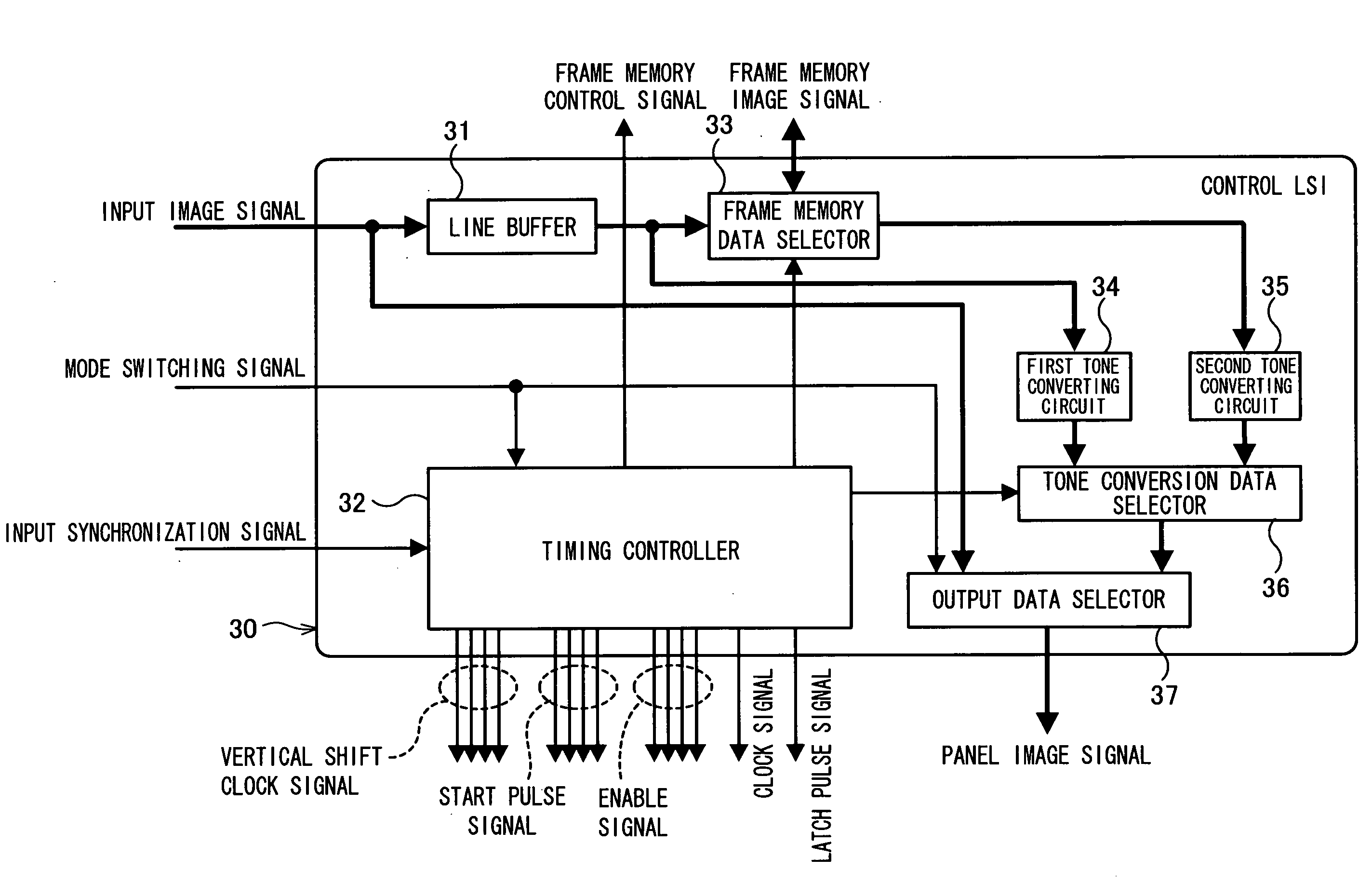
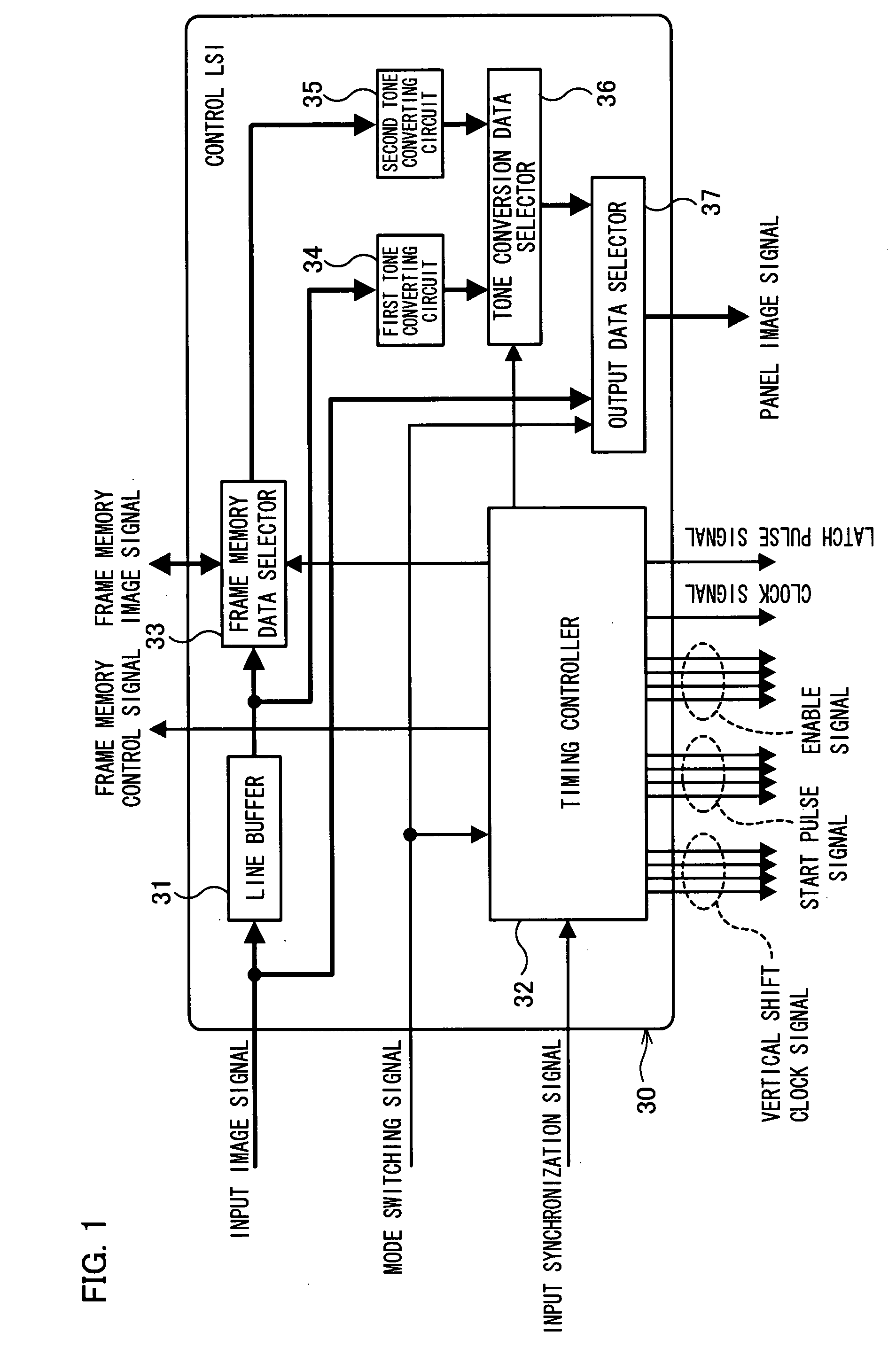
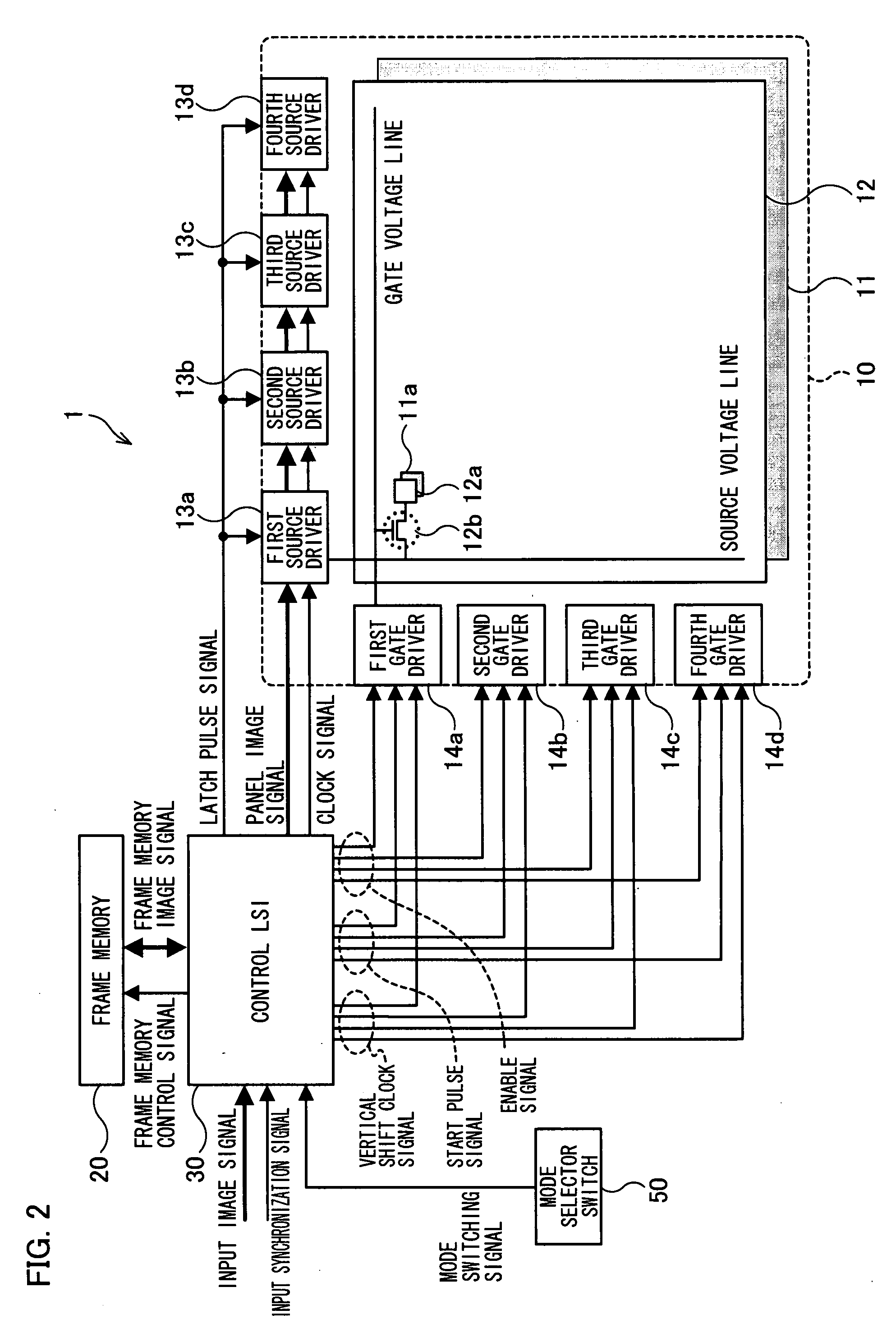
[0060]The following will describe an embodiment of the present invention with reference to FIGS. 1 through 6. To begin with, the structure of an image display apparatus of First Embodiment is schematized below with reference to FIG. 2. In FIG. 2, an image display apparatus 1 includes a display panel 10, a frame memory 20, a control LSI 30, and a mode selector switch 50.

[0061]The display panel 10 constitutes image display means and has a display element array 11, a TFT substrate 12, source drivers 13a through 13d, and gate drivers 14a through 14d. On the display element array 11, a plurality of display elements 11a (pixel sections) made of liquid crystal material or organic electroluminescent material are arranged in a matrix manner.

[0062]In a display area of the TFT substrate 12, respective pixel electrodes 12a and respective TFTs 12b are arranged in a matrix manner so as to correspond to the display elements 11a. The pixel electrodes 12a drive the display elements 11a. The TFTs 12b...

second embodiment

[0107]An image display apparatus of Second Embodiment is the one as illustrated in FIG. 7. An image display apparatus 2 illustrated in FIG. 7 is different from the image display apparatus 1 illustrated in FIG. 2 in that the image display apparatus 2 does not include the mode selector switch 50 and includes a control LSI 60, instead of the control LSI 30. Except for these differences, the structure of the image display apparatus 2 is identical with that of the image display apparatus 1. As such, members having the same structures and operations as those of the image display apparatus 1 are given the same reference numerals shown in FIG. 2, and detailed explanations thereof are omitted.

[0108]In the image display apparatus 2, the control LSI 60 determines whether an image to be displayed is a moving image or a still image on the basis of an input image signal, and the control LSI 60 selects a suitable display mode according to a result of the determination. More specifically, the time-...

third embodiment

[0114]An image display apparatus of Third Embodiment is nearly identical in structure with the image display apparatus 2 illustrated in FIG. 7, but includes a control LSI 70 illustrated in FIG. 9, instead of the control LSI 60. The control LSI 70 includes a luminance measuring circuit 71, instead of the moving / still image determining circuit 61, as opposed to the control LSI 60 illustrated in FIG. 8.

[0115]In the image display apparatus of Third Embodiment, the control LSI 70 measures (calculates) average luminance of an input image signal, and then selects a suitable display mode according to a result of the measurement. More specifically, in the case of the time-division driving performed by the image display apparatus of the present invention, it is generally easy to recognize flickers when luminance of an image to be displayed is high, but it is difficult to recognize flickers when luminance of an image to be displayed is low. As such, it is preferable that in a case where lumina...


PUM


Abstract

In the first display mode, a first tone converting circuit and a second tone converting circuit of a control LSI divide one frame period of an input image signal into a plurality of sub-frame periods to perform output to a display panel, thus realizing image display performed by time-division driving (pseudo-impulse driving). In the second display mode, the control LSI directly outputs an input image signal to the display panel, thus realizing image display performed by hold driving. In at least one embodiment, switching between the first display mode and the second display mode is performed by changing output of an output data selector according to a mode switching signal. This realizes an image display apparatus which effectively obtains the effect of suppressing blurring of a moving image and alleviates the problem of flickers caused by pseudo-impulse driving.

Description

TECHNICAL FIELD[0001]The present invention relates to an image display apparatus including a hold-type display element therein, such as a liquid crystal display element or an EL (Electro Luminescence) display element.BACKGROUND ART[0002]In recent years, in addition to CRT (cathode-ray tube) display apparatuses, various kinds of displays, such as liquid crystal display apparatuses, plasma display apparatuses, and organic electroluminescent display apparatuses have been developed and commercialized.[0003]In display apparatuses, such as CRT display apparatuses, which perform impulse-type display (display carried out during a light-emission period only), pixels carry out black display during a non-selected period. Meanwhile, hold-type display apparatuses (which holds an image of a previous frame until a new image is written) such as liquid crystal display apparatuses and organic electroluminescent display apparatuses, display data previously written is held by pixels during a non-select...

Claims


Application Information

Patent Timeline
Patent Type & Authority Applications(United States)
IPC IPC(8): H04N5/66H04N5/44
CPCG09G3/2011G09G3/2025G09G3/2081G09G3/3208G09G3/3611G09G2310/08G09G2360/16G09G2320/0261G09G2320/0271G09G2320/0606G09G2320/0613G09G2320/0673G09G2320/103G09G2320/0247
Inventor INOUE, AKIHIKOKUMAKURA, TAKESHISHIGETA, MITSUHIROSHIRAISHI, TAI
Owner SHARP KK
Why Eureka
Try Eureka