Sense Amplifier Biasing Method and Apparatus

a biasing method and amplifier technology, applied in the field of sense amplifier biasing method and apparatus, can solve the problems of unreliability of ssa circuitry, inability of cross-coupled differential amplifiers to reliably sense voltage difference, and inability to reliably operate ssa circuitry

Inactive Publication Date: 2009-05-14
POLARIS INNOVATIONS
View PDF15 Cites 25 Cited by
  • Summary
  • Abstract
  • Description
  • Claims
  • Application Information

AI Technical Summary

Problems solved by technology

The cross-coupled differential amplifiers cannot reliably sense the voltage difference unless provided sufficient current.
If even a single current source transistor is improperly biased, the SSA circuitry functions unreliably.
However, process variation ensures that all current source transistors will not have the same operating characteristics such as threshold voltage.
The SSA circuitry will not function properly unless the current source transistors with a high threshold voltage are bia

Method used


Image

  • Sense Amplifier Biasing Method and Apparatus
  • Sense Amplifier Biasing Method and Apparatus
  • Sense Amplifier Biasing Method and Apparatus

Examples


Embodiment Construction

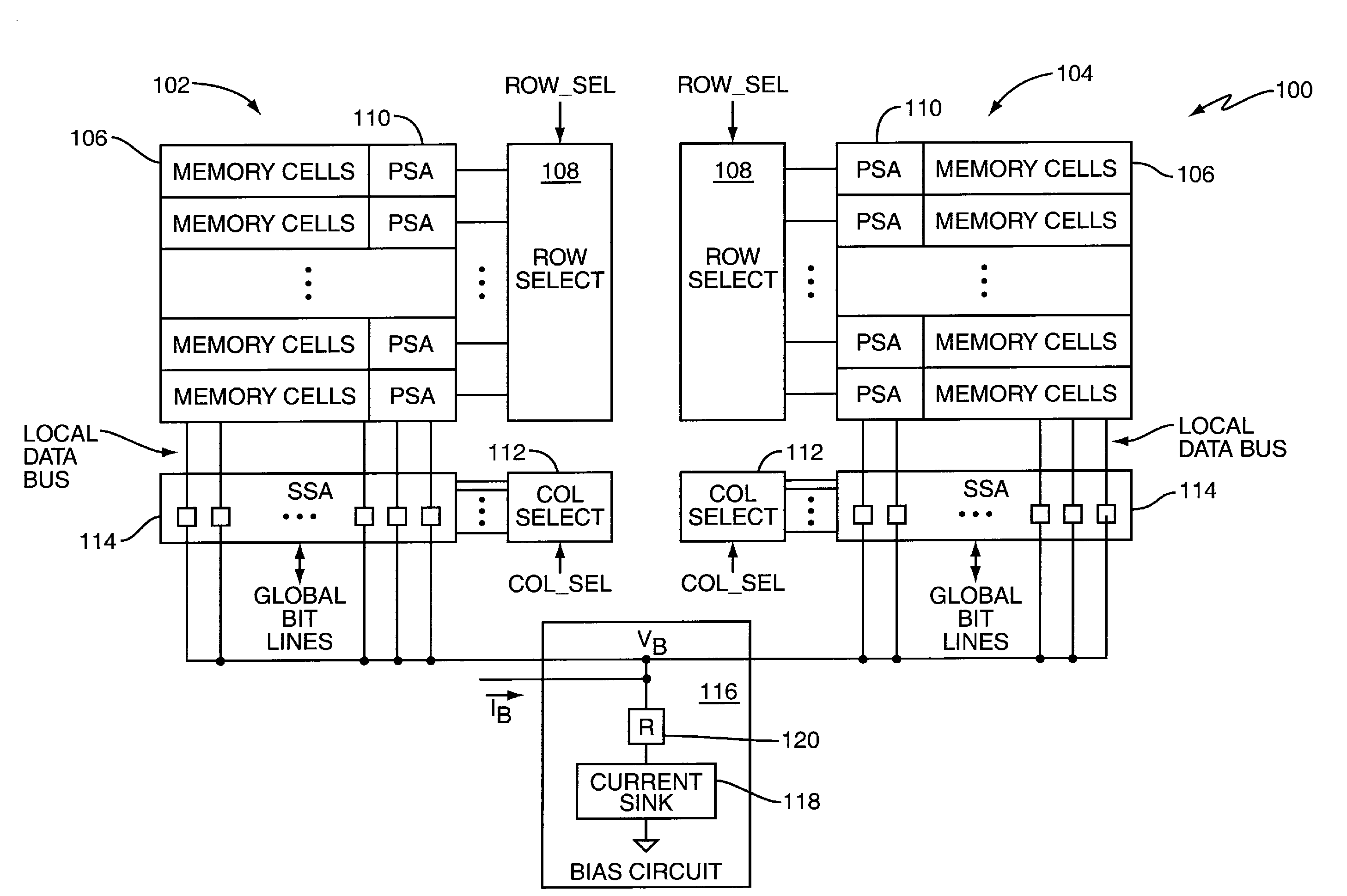
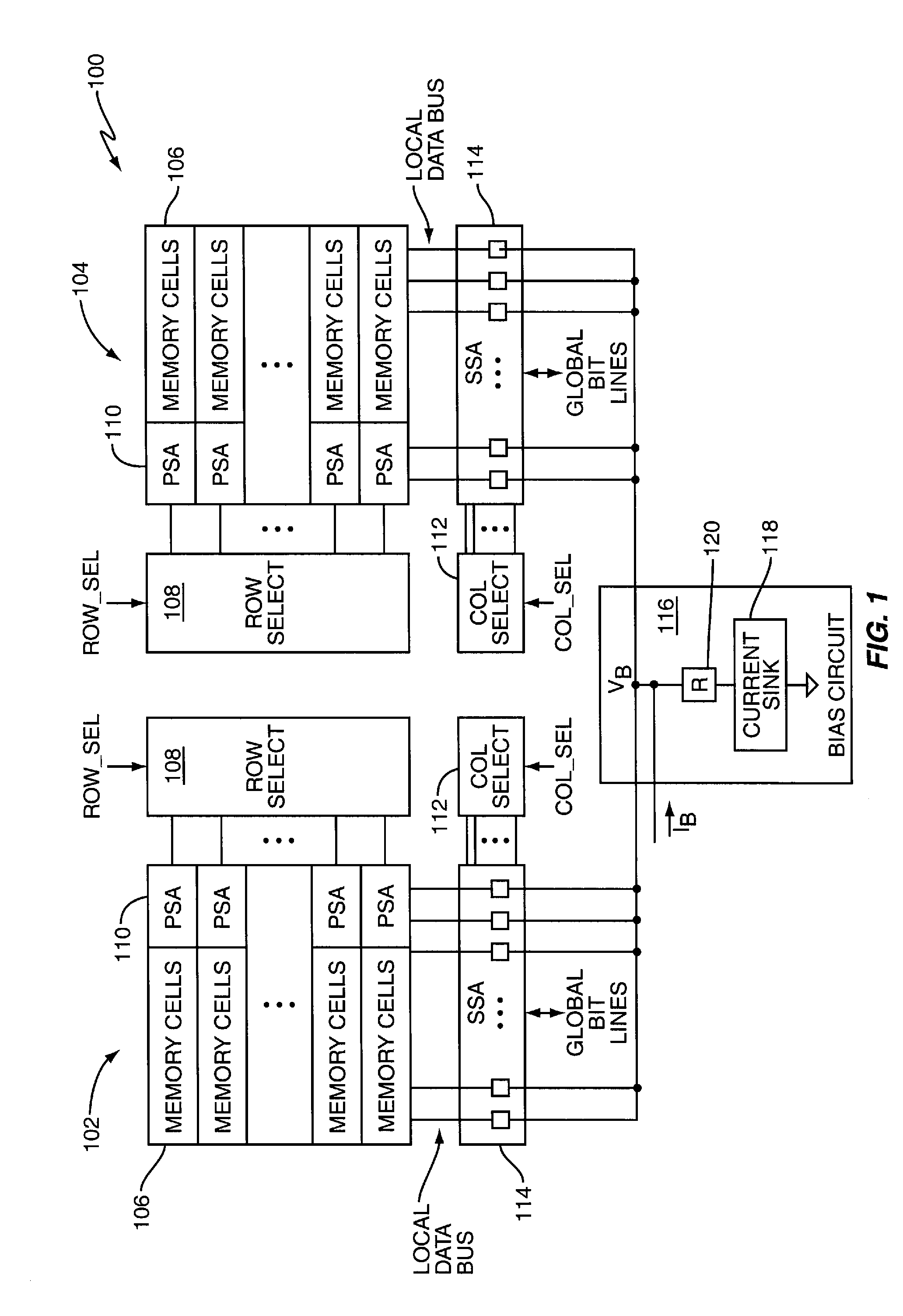
[0010]FIG. 1 illustrates an embodiment of a memory device 100 including two memory arrays 102, 104. In other embodiments, the memory device 100 may include more or less memory arrays. Regardless, each memory array 102, 104 is arranged as one or more logical banks of memory cells 106 such as Dynamic RAM (DRAM), Ferroelectric RAM (FRAM), Magnetoresistive RAM (MRAM), Phase-change RAM (PRAM) or similar types of cells. Row, column and bank address information received by the memory device 100 indicates which memory array row and column location is to be accessed during memory operations (and bank if the arrays are so arranged).

[0011]During read operations, decoded row address information (ROW_SEL) is provided to row select circuitry 108 coupled to the memory arrays 102, 104. The decoded row address information indicates which row of memory cells 106 within one or both of the arrays 102, 104 is to be activated during a read operation. Primary Sense Amplifier (PSA) circuitry 110 located ne...


PUM


Abstract

A memory device comprises sense amplifier circuitry, a current sink and a resistive element. The sense amplifier circuitry is operable to evaluate data read from a memory array included in the memory device responsive to a bias voltage applied to the sense amplifier circuitry. The current sink is operable to sink a bias current. The resistive element couples the current sink to the sense amplifier circuitry. The bias voltage applied to the sense amplifier circuitry corresponds to the voltage drop across the resistive element and current sink as induced by the bias current.

Description

BACKGROUND OF THE INVENTION[0001]Many types of memory devices such as Dynamic Random Access Memory (DRAM) devices store information in memory cells arranged as one or more arrays of selectable rows and columns. Lines connecting each row are commonly referred to as word lines. Each column typically comprises two bit lines, each bit line connected to every other memory cell in the column. To accommodate high density memory demands, two levels of sense amplifier circuitry are typically used to read data out of a memory array and off chip. Primary Sense Amplifier (PSA) circuitry directly reads data from an activated row in the array and drives the data onto a local data bus. Secondary Sense Amplifier (SSA) circuitry coupled to the local data bus evaluates the data by sensing voltage levels of the local data bus and driving the sensed data onto a global data bus. The desired data is then driven off chip.[0002]Conventional SSA circuitry typically comprises pairs of cross-coupled different...

Claims


Application Information

Patent Timeline
IPC IPC(8): G11C7/06G11C11/00
CPCG11C7/02G11C7/062G11C2207/065G11C11/4091G11C7/1048
Inventor RYU, HOON
Owner POLARIS INNOVATIONS
Why Eureka
Try Eureka