Despreading circuit and electronic apparatus

Inactive Publication Date: 2009-05-14
FUJITSU LTD
View PDF5 Cites 0 Cited by
  • Summary
  • Abstract
  • Description
  • Claims
  • Application Information

AI Technical Summary

Benefits of technology

[0016]The despreading circuit and the electronic apparatus thus configured

Problems solved by technology

Using different despreaders in this way is not desirable because the amount of circuitry increases.
While a technique for reducing the amount of circuitry compared with the prior art, regardless of the number o

Method used


Image

  • Despreading circuit and electronic apparatus
  • Despreading circuit and electronic apparatus
  • Despreading circuit and electronic apparatus

Examples


Embodiment Construction

[0021]An embodiment will be described below with reference to drawings, but before that, an explanation will be given of the reason why HS-PDCH and PCPICH cannot be simply processed by a single FHT circuit.

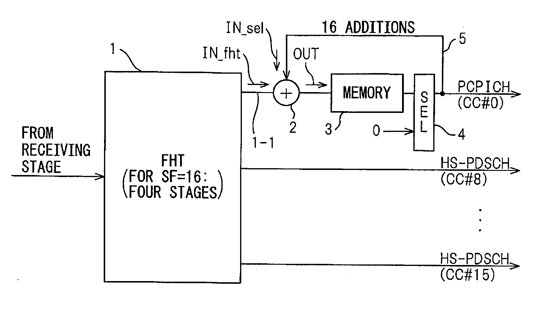
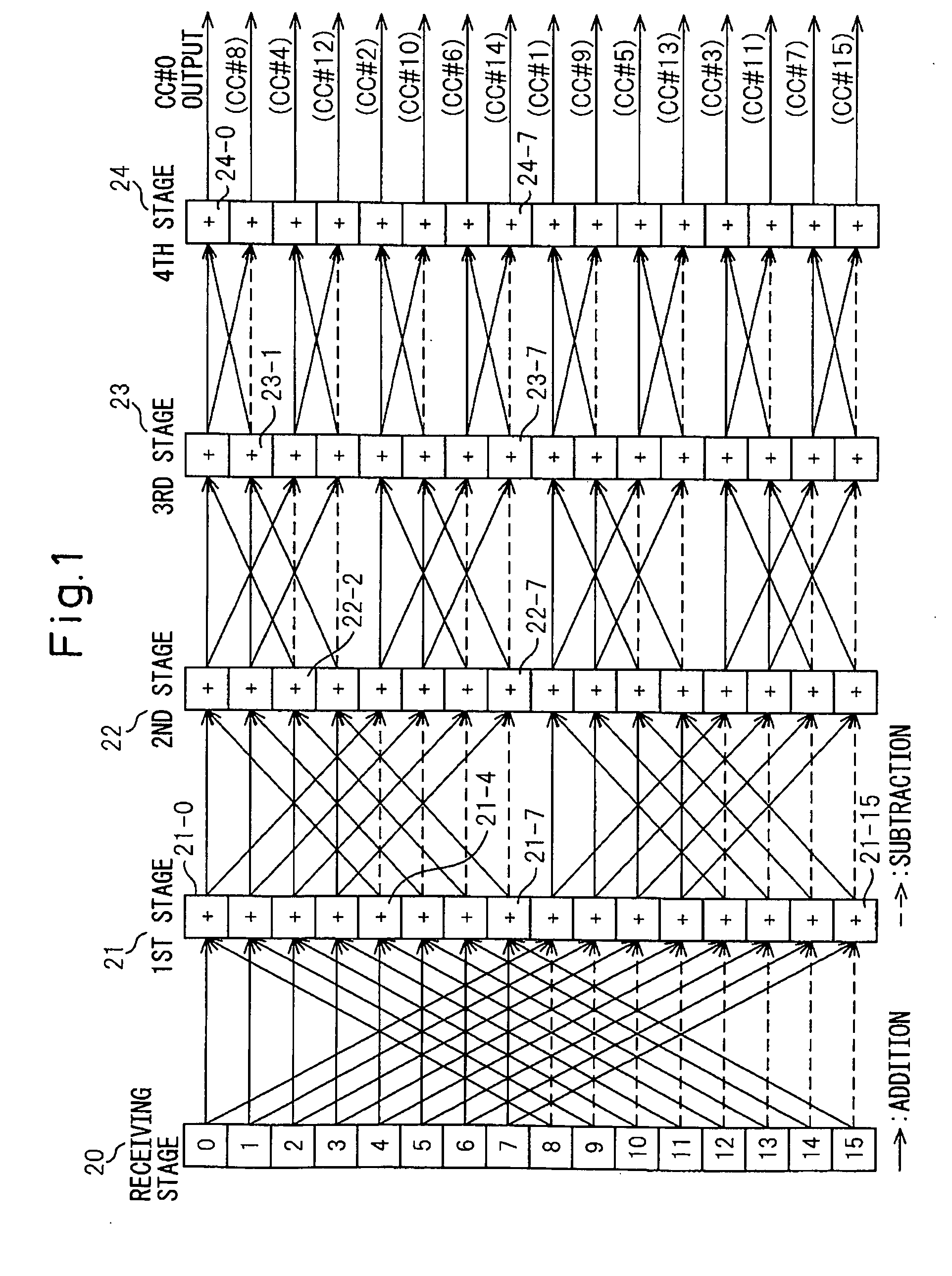
[0022]FIG. 1 is a diagram showing a computation procedure performed by an FHT circuit dedicated to HS-PDSCH whose spreading factor (SF) is 16 (SF=16), as an example of the present embodiment. Generally, the FHT circuit is constructed by combining a plurality of stages of butterfly computation circuits. The number of stages necessary for despreading differs depending on the spreading factor. Since the spreading factor (SF) of the HS-PDSCH is 16, four butterfly computation stages become necessary in the FHT circuit. As shown in FIG. 1, the FHT circuit dedicated to HS-PDSCH comprises a receiving stage 20 and first to fourth stages 21 to 24. With this configuration, the results of despreading corresponding to all the channelization codes CC#0 to CC#15 are output at the fourth stage.

[0...


PUM


Abstract

For channelization codes CC#1 to CC#15, the despreading circuit comprises an FHT circuit with a spreading factor of 16 which outputs the results of despreading of an HS-PDCH. An adder is connected to the FHT circuit at an output terminal thereof corresponding to channelization code CC#0. The adder is connected to a memory to which is input the value obtained by adding an output of the FHT circuit to an output of a selector connected to the memory via a feedback line. By performing the addition 16 times in the adder, the result of despreading of a PCPICH is output.

Description

BACKGROUND OF THE INVENTION[0001]1. Field of the Invention[0002]The present invention relates to a despreading circuit that receives a spread-spectrum signal and despreads the received signal at the receiving end, and an electronic apparatus incorporating the same.[0003]2. Description of the Related Art[0004]In recent years, communication services using High Speed Downlink Packet Access (HSDPA), a high-speed packet communication standard developed as an extension of W-CDMA (Wideband Code Division Multiple Access), have come to be provided as high-speed communication services for mobile telephones, personal computers, etc. In the services provided using HSDPA, different maximum communication speeds are defined for different service categories, and the communication speed changes according to the communication environment.[0005]In HSDPA, each terminal receives packet data via a High Speed Physical Downlink Shared Channel (HS-PDSCH). Generally, in CDMA systems, one channel is coded by ...

Claims


Application Information

Patent Timeline
IPC IPC(8): H04B1/69H04B7/216H04B1/707H04B1/709
CPCH04B1/7093H04B2201/70701H04B2001/70935
Inventor FUKUSHIMA, KENTARO
Owner FUJITSU LTD
Why Eureka
Try Eureka