
On-vehicle stretcher and litter

a technology for a stretcher and a vehicle, applied in the field of stretchers, can solve the problems that the satisfaction of the stretcher and the litter have not yet been realized, and achieve the effects of maintaining the safety of the patient on the litter, and reducing the risk of injury

Active Publication Date: 2009-05-14
MATUNAGA MANUFACTORY
View PDF15 Cites 2 Cited by
  • Summary
  • Abstract
  • Description
  • Claims
  • Application Information

AI Technical Summary

Benefits of technology

[0023]The constant load spring serving as a slide mechanism for changing the position of the upper frame vertically and the pin lock mechanism for fixing the upper frame having been moved vertically at an arbitrary position are used. Therefore, the height of the stretcher can be adjusted quietly and quickly.
[0024]The lock supporter that is adjustable longitudinally and vertically so as to match the lock piece for fixing the stretcher installed on the cargo bed of the patient carrying automobile is installed in the bottom part of the stretcher. Therefore, even if the type of patient carrying automobile is changed, the height and the longitudinal position of the lock supporter can be adjusted easily.
[0025]The shielding plate capable of being unlocked from any of three directions of the right, left, and upper parts is provided at the side of the litter. Therefore, the safety of the patient on the litter can be maintained by closing the shielding plate, and also the shield plate is unlocked from any of three directions of the right, left, and upper parts, by which the patient can be put on or down easily and medical treatment such as examination with a stethoscope and drip-feeding can be performed easily.
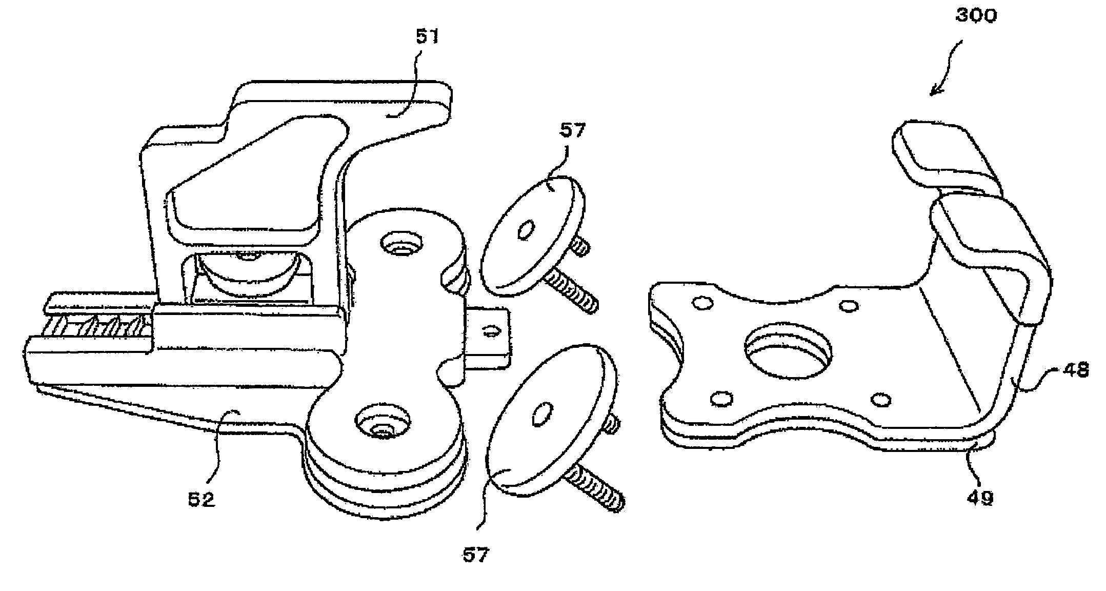
[0026]The fixture consisting of the front hook installed in the front part of cargo bed of the ambulance or the like and the lock plate installed in the rear part of the cargo bed gently receives the front part of the stretcher by means of the front hook, and reliably fixes the rear part of the stretcher placed on the ambulance or the like by means of the lock piece engaging with the lock supporter of the lock plate installed in the rear part. Also, the fixture has a construction such that it can be released easily and the stretcher can be taken out easily.

Problems solved by technology

Although the stretcher and the litter placed on the stretcher have been improved variously, a satisfactory stretcher and a satisfactory litter have not yet been realized.

Method used


Image

  • On-vehicle stretcher and litter
  • On-vehicle stretcher and litter
  • On-vehicle stretcher and litter

Examples


Embodiment Construction

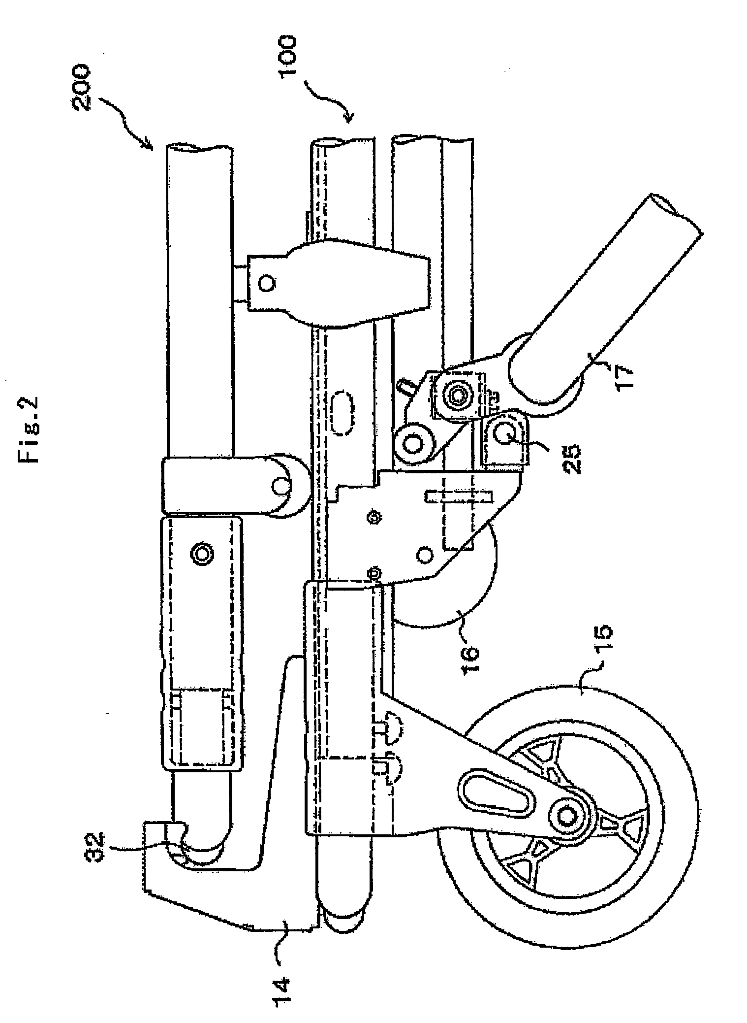
[0104]A stretcher placed on a patient carrying automobile and a litter placed on the stretcher in accordance with the present invention will now be described in detail with reference to the accompanying drawings. The present invention is not limited to an example described below. Also, the patient carrying automobile on which the stretcher and the litter in accordance with the present invention are placed is not limited to an ambulance for receiving and carrying a patient in case of emergency. The patient carrying automobile includes a vehicle capable of placing the stretcher, such as a motor hearse, in addition to the ambulance provided with equipment (referred to as “a stretcher”) for carrying a patient etc. when the patient etc. enter or leave a medical institution, go to a hospital regularly, transfer to another hospital, or are picked up and dropped off at a social welfare facility etc.

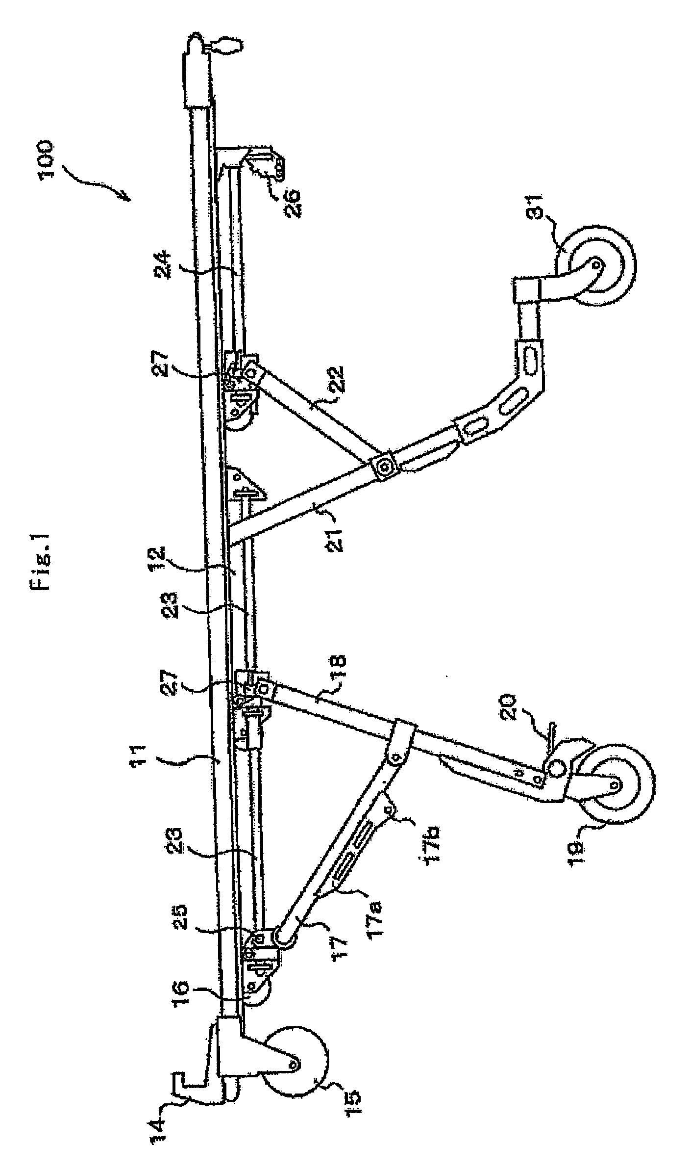
[0105]As shown in FIG. 1, a stretcher 100 in accordance with the present invention includes, ...


PUM


Abstract

A stretcher fixture installed on the floor surface of the cargo bed of an ambulance or the like to fix a stretcher on the cargo bed of the ambulance or the like, characterized by having a front hook which is mounted on the front floor surface of the cargo bed of an ambulance or the like to fix the front part of the stretcher; and a lock plate which is installed on the rear floor surface and has a lock piece engaging with a lock supporter installed in the rear part of the stretcher.

Description

CROSS REFERENCE TO RELATED APPLICATIONS[0001]The present application is a divisional application of U.S. patent application Ser. No. 11 / 821,732, filed Jun. 25, 2007, the entire contents of which are incorporated herein by reference and priority to which is hereby claimed. application Ser. No. 11 / 821,732 is a continuation-in-part application of International application JP PCT / JP2005 / 014641 filed Aug. 10, 2005, priority to which is claimed herein and the contents of which are incorporated herein by reference. The PCT / JP2005 / 014641 application claimed the benefit of the dates of the earlier filed Japanese Patent Application Nos. JP2004-373729 filed Dec. 24, 2004 and JP2005-183337 filed Jun. 23, 2005, the entire contents of each of which are incorporated herein by reference, and priority to each of which is hereby claimed.TECHNICAL FIELD[0002]The present invention relates to a stretcher placed on an ambulance or the like and a litter placed on the stretcher. More particularly, it relat...

Claims


Application Information

Patent Timeline
Patent Type & Authority Applications(United States)
IPC IPC(8): B60P3/06
CPCA61G1/017A61G3/0816A61G1/0262A61G1/0268A61G1/0293A61G1/0562A61G1/0565A61G3/0875A61G3/0891A61G7/0507A61G2007/051A61G1/0237A61G1/0287A61G2001/042A61G1/0212A61G1/042A61G7/051A61G1/00A61G1/02A61G1/06
Inventor MATUNAGA, SIGEYUKIMATUNAGA, NORIYUKIGOTO, KAZUYUKI
Owner MATUNAGA MANUFACTORY
Learn More