Vacuum pump with a lubricant pump

Active Publication Date: 2009-05-14
PFEIFFER VACUUM GMBH
View PDF13 Cites 1 Cited by
  • Summary
  • Abstract
  • Description
  • Claims
  • Application Information

AI Technical Summary

Benefits of technology

[0012]For a constant flow of the lubricant to the inlet of the helical channel, it is advantageous when a structure that delivers lubricant under action of a centrifugal source, is located between the shaft section and the helical channel. A constant feeding flow is achieved when an angle that differs from zero, is formed between the direction of the gravity force and the rotor axis. In this case, metal chips, the specific weight of which is greater than that of the lubricant, would be accelerated outwardly by the centrifugal force and would not enter the helical channel.
[0013]Advantageously, the delivery structure includes a cone, a small diameter of which corresponds to the diameter of the shaft section and a large diameter of which corresponds to the diameter of the another section. This provides for a simple and cost-effective manufacturing of the vacuum pump.
[0014]According to a further advantageous embodiment of the invention, the lubricant pump includes an axial slide bearing provided at an end of the rotor remote from the helical channel and lubricated by the feedable lubricant. Thereby, the axial forces, which are generated by the feedable lubricant, are used for pressing the rotor int

Problems solved by technology

A poor supply can, however, enda

Method used


Image

  • Vacuum pump with a lubricant pump
  • Vacuum pump with a lubricant pump
  • Vacuum pump with a lubricant pump

Examples


Example

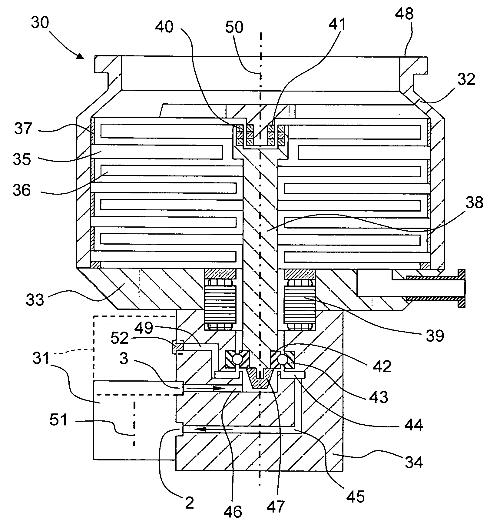
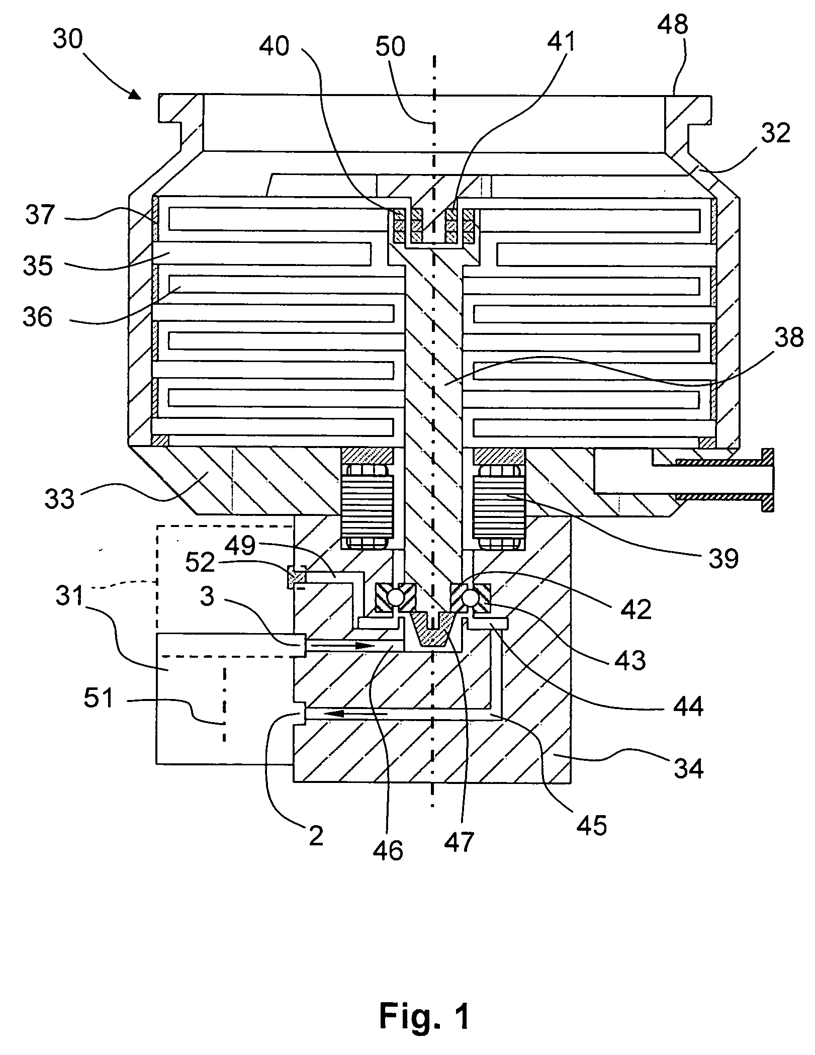
[0022]A vacuum pump 30 according to the present invention, which is shown in FIG. 1 together with a lubricant pump 31, has a multi-part housing. Pump-active components of the vacuum pump 30 are located in a first, high vacuum-side housing part 32. The housing part 32 is connectable by a flange 48 and by connection elements (not shown) with a recipient. The pump-active components include stator discs 35 and rotor discs 36 which carry vanes and are arranged in several planes. The stator discs 35 are axially spaced from each other by spacer rings. Instead of vanes, other pump-active structures can be used, e.g., the structures according to Holweck and Siegbahn. The rotor discs 36 are mounted on a rotor shaft 38 at an axial distance from each other. The stator discs 35 extend into spaces defined by the axial distances between the rotor discs 36. A drive 39 rapidly rotates the rotor shaft 38. In order to achieve a desired pumping effect, the rapid rotational speed lies in a range of tens...


PUM


Abstract

A vacuum pump includes a quick-rotatable component a bearing for supporting the quick-rotatable component and a lubricant pump for feeding lubricant to the bearing and having a rotor, with the bearing and the lubricant pump forming parts of a closed lubrication circuit having a hollow axle on which the rotor of the lubricant pump is rotatably supported.

Description

BACKGROUND OF THE INVENTION[0001]1. Field of the Invention[0002]The present invention relates to a vacuum pump having a bearing for supporting a quick-rotatable shaft, a lubricant pump having a rotor with at least one structure for producing a pumping-action, and a closed lubricant circuit in which the bearing and the lubricant pump are arranged.[0003]2. Description of the Prior Art[0004]Vacuum pumps with quick-rotatable components find today numerous industrial applications. In vacuum pumps designed for operation in the molecular flow region and for producing high-vacuum, the rapid rotational speed of these components lies in a range of tens of thousands revolutions per minute. In the state-of-the-art, two types of bearings are used for supporting these quick-rotatable components. To one type relate magnetic bearings which can be formed as passive or active magnetic bearing. To the other type relate precision roller bearings. A precision roller bearing requires lubrication to keep ...

Claims


Application Information

Patent Timeline
IPC IPC(8): F04C29/02
CPCF04D17/168F04D19/042F16C33/6659F04D29/063F16C33/1045F04D29/059F16C2360/45
Inventor EILERS, MARTINWILLIG, MICHAEL
Owner PFEIFFER VACUUM GMBH
Why Eureka
Try Eureka