Thermoelectric half-cell and method of production

a technology of thermoelectric half cells and half cells, which is applied in the direction of thermoelectric device junction materials, thermoelectric device manufacturing/treatment, and thermoelectric device with peltier/seeback effect, etc., can solve the problems of serious degradation of semiconductors, and achieve the effect of high thermal conversion efficiency, simple and cost-effectiv

Active Publication Date: 2022-05-31
TEGMA
View PDF13 Cites 0 Cited by
  • Summary
  • Abstract
  • Description
  • Claims
  • Application Information

AI Technical Summary

Benefits of technology

[0024]The main objective of the present invention is to provide a simple and cost-effective manufacturing method of a thermoelectric half-cell having high thermal conversion efficiency and a thermoelectric half-cell made by the method.

Problems solved by technology

The document discloses further that at 850 K, the vapour pressure of Sb is about 10 Pa, leading to a serious degradation of the semiconductor due to loss of the element Sb.

Method used


Image

  • Thermoelectric half-cell and method of production
  • Thermoelectric half-cell and method of production
  • Thermoelectric half-cell and method of production

Examples


example embodiment

OF THE INVENTION

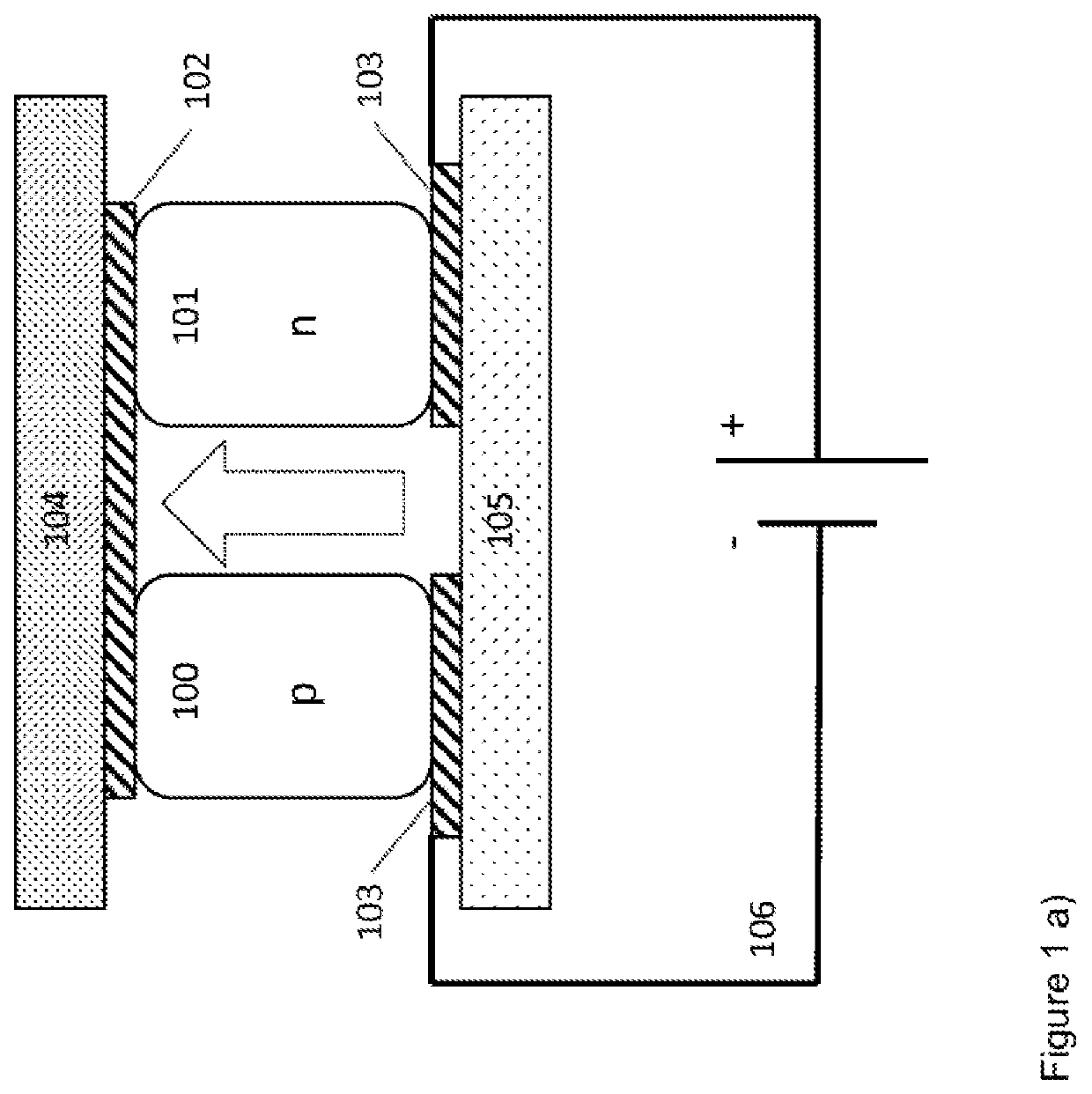
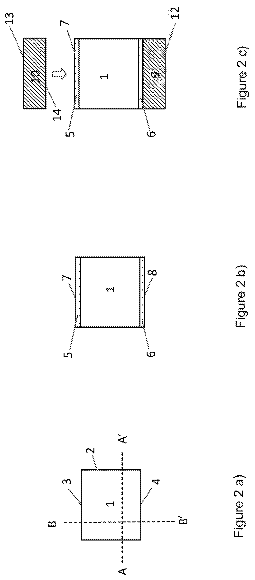
[0129]The invention is described in more detail by way of an example embodiment of a thermoelectric cell according to the first, second, third and fourth aspect of the invention.

[0130]The example embodiment utilises a filled or non-filled CoSb3-based skutterudite as the semiconducting thermoelectric conversion material intended to operate at high temperatures, i.e. at temperatures in the range from about 0° C. up to about 800° C. Each element in the example embodiment is provided with the ADA-structured adhesion layer and the contact substrates are bonded to the element including the ADA-structured adhesion layer by a SLID-bonding. Both the first and the second adhesion film of the ADA-structure is made of one of Cr, Ta or Ti. An especially preferred embodiment is Ti of at least 99.5 weight % pure Ti. The diffusion barrier layer is a nitride of the same metal as employed in the adhesion films. Thus, the especially preferred ADA-structure comprises a first adhesion fi...


PUM

PropertyMeasurementUnit
thicknessaaaaaaaaaa
thicknessaaaaaaaaaa
thicknessaaaaaaaaaa

Abstract

The present invention relates to a method for manufacturing a thermoelectric half-cell which utilises the metallization for obtaining both the electric and thermal contact required to form a functional thermoelectric cell.

Description

[0001]The present invention relates to a manufacturing method of sealed high-temperature thermoelectric elements, and thermoelectric elements made thereof.BACKGROUND[0002]A thermoelectric element converts a fraction of heat energy flowing through the element as a function of the size of the heat flux through the element and the Seebeck coefficient of the thermoelectric material of the element.[0003]The Seebeck effect is one of three possible expressions of the thermoelectric effect, namely the direct conversion of thermal energy to electric energy found in some materials when subject to a temperature gradient creating a heat flux through the material. The Seebeck effect will, when connecting the material to a heat sink on one side and a heat source on the opposite side, create an electric potential which may be utilised for driving an electrical device or charging a battery. The thermoelectric conversion efficiency is dependent on the materials Seebeck coefficient and ratio electric...

Claims


Application Information

Patent Timeline
Patent Type & Authority Patents(United States)
IPC IPC(8): H01L35/08H01L35/32H01L35/18H01L35/22H01L35/34
CPCH01L35/34H01L35/08H01L35/18H01L35/22H01L35/32H10N10/817H10N10/853H10N10/855H10N10/01H10N10/17
Inventor LARSSON, ANDREASTOLLEFSEN, TORLEIF A
Owner TEGMA
Why Eureka
Try Eureka