Golf stance and ball alignment guide

a technology for golfers and stances, applied in golf tees, golfing accessories, golf clubs, etc., can solve the problems of increasing the chances of a “squarely hit” ball, and achieve the effects of minimal or no chance of injury, easy carrying and storage, and no damage to the ma

Inactive Publication Date: 2009-05-14
ALTER HOBART L
View PDF15 Cites 8 Cited by
  • Summary
  • Abstract
  • Description
  • Claims
  • Application Information

AI Technical Summary

Benefits of technology

[0014]Peg members may be provided with the device for pinning one of the elongated members to a practice mat. Whereas a golf tee will not be effective in holding down the preferred device on a practice mat, the pointed end of each preferred peg member is adapted to removably stick into the practice mat effectively and without damage to the mat. The peg members are adapted to attach to at least one of the elongated members, so that, when the elongated members are in storage configuration, the peg members are connected to, and easily carried along and stored with, the rest of the device with minimal or no chance or injury by the points of the peg members. Golf tees may be used to secure the device to the ground.
[0015]The preferred embodiments of the invented guide comprise entirely or substantially slender and light-weight components. The preferred tubular elongated members are small in diameter, compared for example, to the diameter of a golf ball, and are preferably substantially smooth along most of their outer surfaces. The intersection member is preferably simple and preferably has no moving parts and no connection means

Problems solved by technology

The above guidelines for stance and ball placement typically result in the golfer's feet, hips, and shoulders be

Method used


Image

  • Golf stance and ball alignment guide
  • Golf stance and ball alignment guide
  • Golf stance and ball alignment guide

Examples


Embodiment Construction

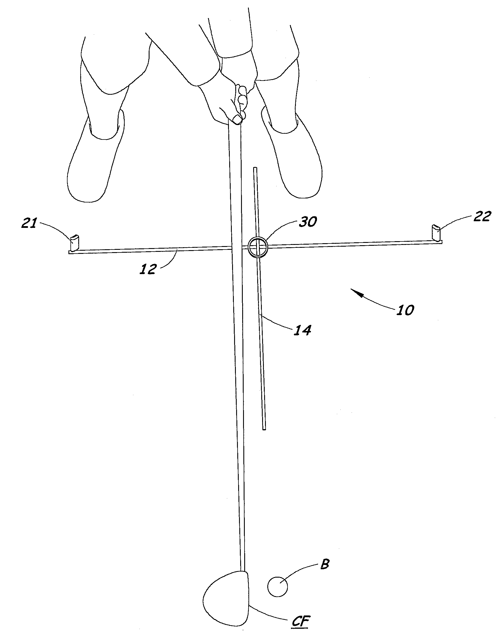
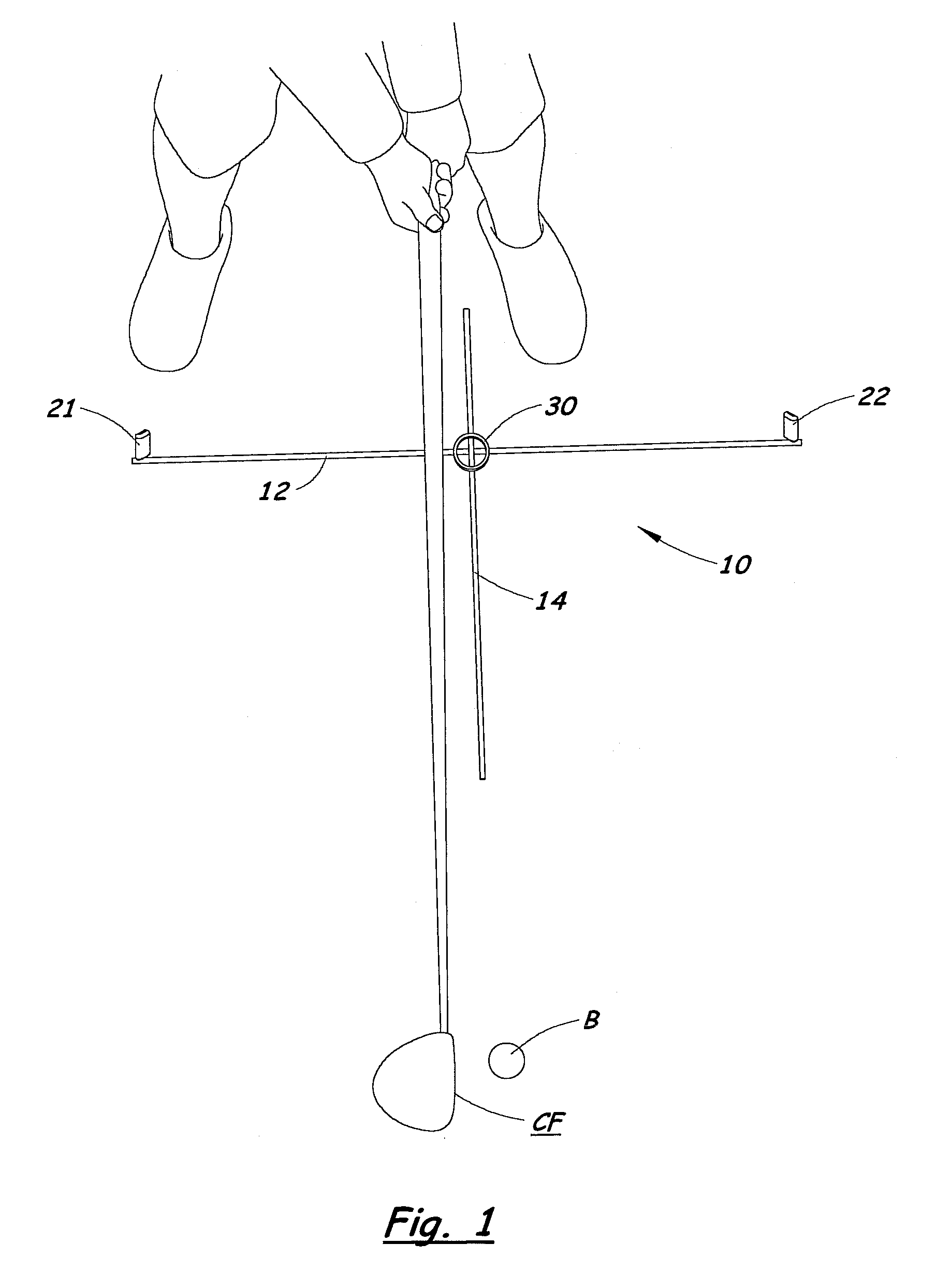
[0030]Referring to the Figures, there are shown two, but not the only, embodiments of the invented guide device for golfers. The preferred device comprises a marker assembly comprising two elongated markers that are laid on, and that indicate, two important lines. These lines comprise a first line that is (for all practical purposes) parallel to the desired line of travel of the golf ball B when accurately hit toward the target, and a second line perpendicular to the first line that extends through the ball. The importance of these two lines is described in the Related Art and Summary of the Invention sections of this document. For convenience, one of the elongated markers may be called a target-pointing marker and the other may be called a ball-pointing marker.

[0031]The preferred marker assembly further comprises a connector that serves to connect the markers in the preferred, perpendicular configuration during use. Preferably, the connector received both markers at or near the loc...


PUM


Abstract

A guide for improving a golfer's stance and swing includes an elongated hollow member, an elongated insert member, and a connector. In golf-practice configuration, the hollow member and the insert member cross each other at 90 degrees and are adjustable relative to each other for different ball placement. In a storage configuration, the insert member is removed from the connector and slid and latched into an interior space of the hollow member. The hollow member and the insert member are preferably tubular so that the storage configuration is generally a tube-within-a-tube. The preferred connector is near the intersection of the hollow member and the insert member but does not require any structure to be between the hollow member and the insert member at or near the place where they cross each other, resulting in a low profile guide. Preferably, only a small portion of the connector contacts the practice mat or ground, resulting in minimal resistance to movement on the mat or ground. Multiple, sharply-pointed pegs may temporarily fix the guide to a mat, and may be connected to the hollow member and/or the insert member for storage of the entire device as a single, compact unit.

Description

BACKGROUND OF THE INVENTION[0001]1. Field of the Invention[0002]The present invention relates to accessories for improvement of a golfer's game, especially by improving the golfer's stance and swing. The invented guide serves as a visual reference for placement of the golfer's feet relative to an imaginary target line and relative to the ball, and squaring of the face of the club to the ball.[0003]2. Related Art[0004]In addressing a golf ball before a swing, a golfer should stand with the toes of both feet on a line parallel to the plane of the desired path of the ball to a target. Therefore, to assist in aligning the user's feet, it is desirable to mark an imaginary target line on the ground, between the golfer's feet and the ball, that points to the target.[0005]In the past, golfers have frequently laid a golf club on the ground as the marker for the imaginary target line. If the golfer stands with the toes of both feet on a line parallel to the marker golf club, and, hence, paral...

Claims


Application Information

Patent Timeline
IPC IPC(8): A63B69/36
CPCA63B57/0018A63B69/3623A63B69/3632A63B69/3661A63B2071/0694A63B2071/024A63B2210/50A63B2210/58A63B69/3667A63B57/10
Inventor ALTER, HOBART L.
Owner ALTER HOBART L
Why Eureka
Try Eureka