Part in die, die change process

a die change and die technology, applied in forging presses, forging/pressing/hammering apparatuses, shape tools, etc., can solve the problems of high machinery cost, large space required for multiple presses, and conventional die change methods, so as to reduce the amount of time taken

Inactive Publication Date: 2009-05-21
HIROTEC AMERICA
View PDF0 Cites 14 Cited by
  • Summary
  • Abstract
  • Description
  • Claims
  • Application Information

AI Technical Summary

Benefits of technology

[0009]Therefore, in the present die change method, the press only has to cycle once to perform a single part run (i.e., work on one workpiece) and to perform a die change. In contrast, in conventional methods, a press has to cycle three times to run one workpiece and to perform a die change. The pre

Problems solved by technology

Use of multiple presses requires a large amount of space and is associated with high machinery c

Method used


Image

  • Part in die, die change process
  • Part in die, die change process
  • Part in die, die change process

Examples


Embodiment Construction

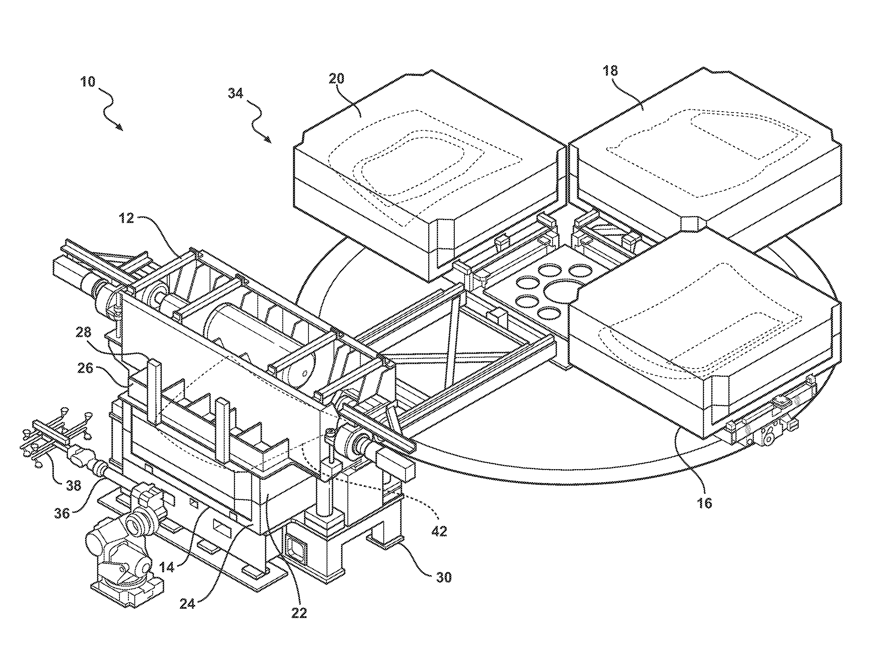
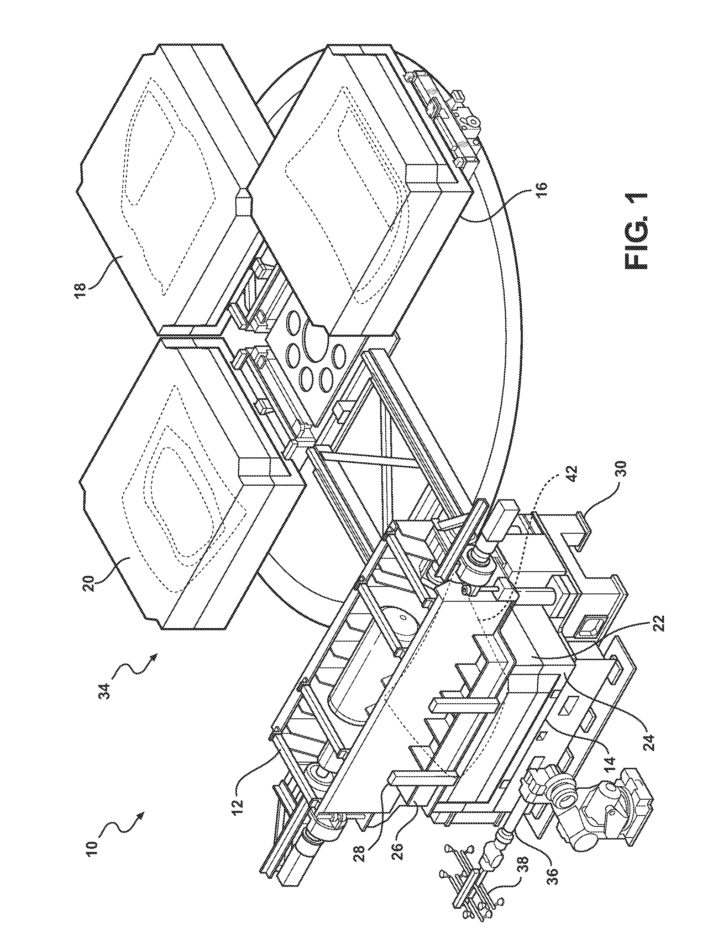
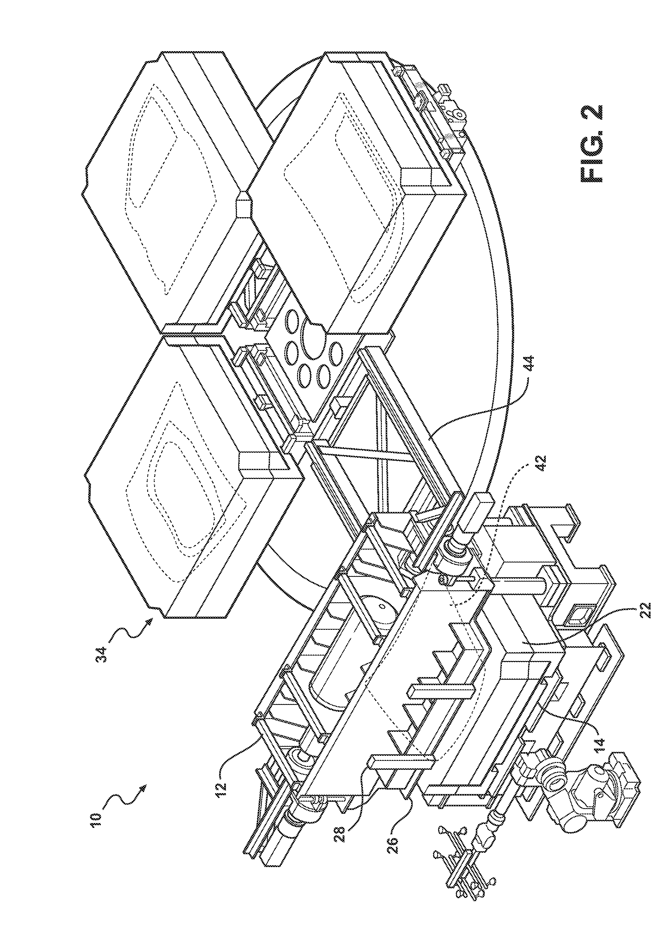
[0025]Referring now to the drawings in detail, numeral 10 generally indicates a rotary die changer and die press system. The system 10 includes a die press 12 and a rotary die changer 34. A home position of the die press 12 is a closed position in which a die in the die press 12 is shut. During a die change process, a workpiece is left in a die that is removed from the die press 12.

[0026]In a specific embodiment shown by example in the drawings, a method according to the invention may be applied to the rotary die changer and die press system 10. In FIG. 1, a first die set 14 is positioned in the die press 12. The first die set 14 includes upper and lower members 22, 24, respectively. The upper member 22 is mounted on a ram 26 of the die press 12, such as by clamps 28 or similar, and the lower member 24 rests on a base 30 of the die press 12. The die press 12 is in a closed, home position as shown wherein the ram 26 is lowered to mate the upper 22 and lower members 24 of the first di...


PUM

PropertyMeasurementUnit
Lengthaaaaaaaaaa
Distanceaaaaaaaaaa

Abstract

A die change method includes providing a press apparatus having a base and a ram, and a first die set including an upper die member and a lower die member. The lower die member is supported on the base and the upper die member is mounted on the ram. The ram is lowered into a closed, home position to mate the upper and lower die members and to perform an operation on a workpiece disposed between the die members. The ram is released from the upper die member. The ram is raised a minimum distance to provide minimal clearance for removing the upper and lower die members from the press. The mated upper and lower die members are moved out of the press with the workpiece held between the upper and lower die members.

Description

CROSS REFERENCE TO RELATED APPLICATION[0001]This application claims the priority of U.S. Provisional Application No. 61 / 003,807 filed Nov. 20, 2007.TECHNICAL FIELD[0002]This invention relates to press and die apparatuses, and more particularly to a die change method for a press and die apparatus.BACKGROUND OF THE INVENTION[0003]It is known in the art relating to flexible assembly systems to use a batch build method or a synchronous method. In a synchronous method, the batch size is one. Synchronous production methods typically use multiple presses without changing the die in any of the presses. Use of multiple presses requires a large amount of space and is associated with high machinery costs. On the other hand, batch production methods, such as in the production of vehicle closure panels, often use press and die hemming apparatuses with die changers. Conventional die change methods, however, are time-consuming and decrease production speed. For example, for automotive closure pane...

Claims


Application Information

Patent Timeline
IPC IPC(8): B21J13/00
CPCB21D22/02B21D37/14B21D37/145Y10T483/10B21J13/02B29C51/26Y10T483/1731B21D39/021
Inventor TOENISKOETTER, JAMES
Owner HIROTEC AMERICA
Why Eureka
Try Eureka