Locking pliers with opposing handle

Inactive Publication Date: 2009-05-21
KAMMERMEIER PAUL
View PDF13 Cites 4 Cited by
  • Summary
  • Abstract
  • Description
  • Claims
  • Application Information

AI Technical Summary

Benefits of technology

[0010]The utility advantages of locking pliers with opposing handle are multiple. Since the opposing handle acts as a second lever arm, the user is able to apply more rotational force to the workpiece. Another great advantage of the invention is to allow the user to more evenly apply the rotating force and thus stabilize the workpiece when turning it, whenever the workpiece is not securely fixed. but tends to move, sway or wiggle when the user attempts to rotate it. Additionally, the locking pliers according to the invention, allow the user to operate in conditions where the work space or the user's reach is limited or obstructed. Once a workpieces is held securely by conventional locking pliers and attempted to be rotated, the handle of the conventional pliers might rotate far enough as to be out of reach of the user. In this case, the user would have to unlock the pliers, reposition them, and then relock them before continuing to rotate the workpiece. Using the locking pliers with opposing handle, according to the present invention, when one handle is turned farther away, the additional handle naturally comes closer, and it can be easier for the user to reach, thus avoiding the need to unlock, reposition, and re-lock the locking pliers. These and various other features as well as advantages, which characterize the present invention, will be apparent from a reading of the following detailed description and a review of the associated drawings.
is to allow the user to more evenly apply the rotating force and thus stabilize the workpiece when turning it, whenever the workpiece is not securely fixed. but tends to move, sway or wiggle when the user attempts to rotate it. Additionally, the locking pliers according to the invention, allow the user to operate in conditions where the work space or the user's reach is limited or obstructed. Once a workpieces is held securely by conventional locking pliers and attempted to be rotated, the handle of the conventional pliers might rotate far enough as to be out of reach of the user. In this case, the user would have to unlock the pliers, reposition them, and then relock them before continuing to rotate the workpiece. Using the locking pliers with opposing handle, according to the present invention, when one handle is turned farther away, the additional handle naturally comes closer, and it can be easier for the user to reach, thus avoiding the need to unlock, reposition, and re-lock the locking pliers. These and various other features as well as advantages, which characterize the present invention, will be apparent from a reading of the following detailed description and a review of the associated drawings.

Problems solved by technology

If the entrance to the work space is too small, the user may be unable to reach the handle in some parts of its turning arc.

Method used


Image

  • Locking pliers with opposing handle
  • Locking pliers with opposing handle
  • Locking pliers with opposing handle

Examples


Embodiment Construction

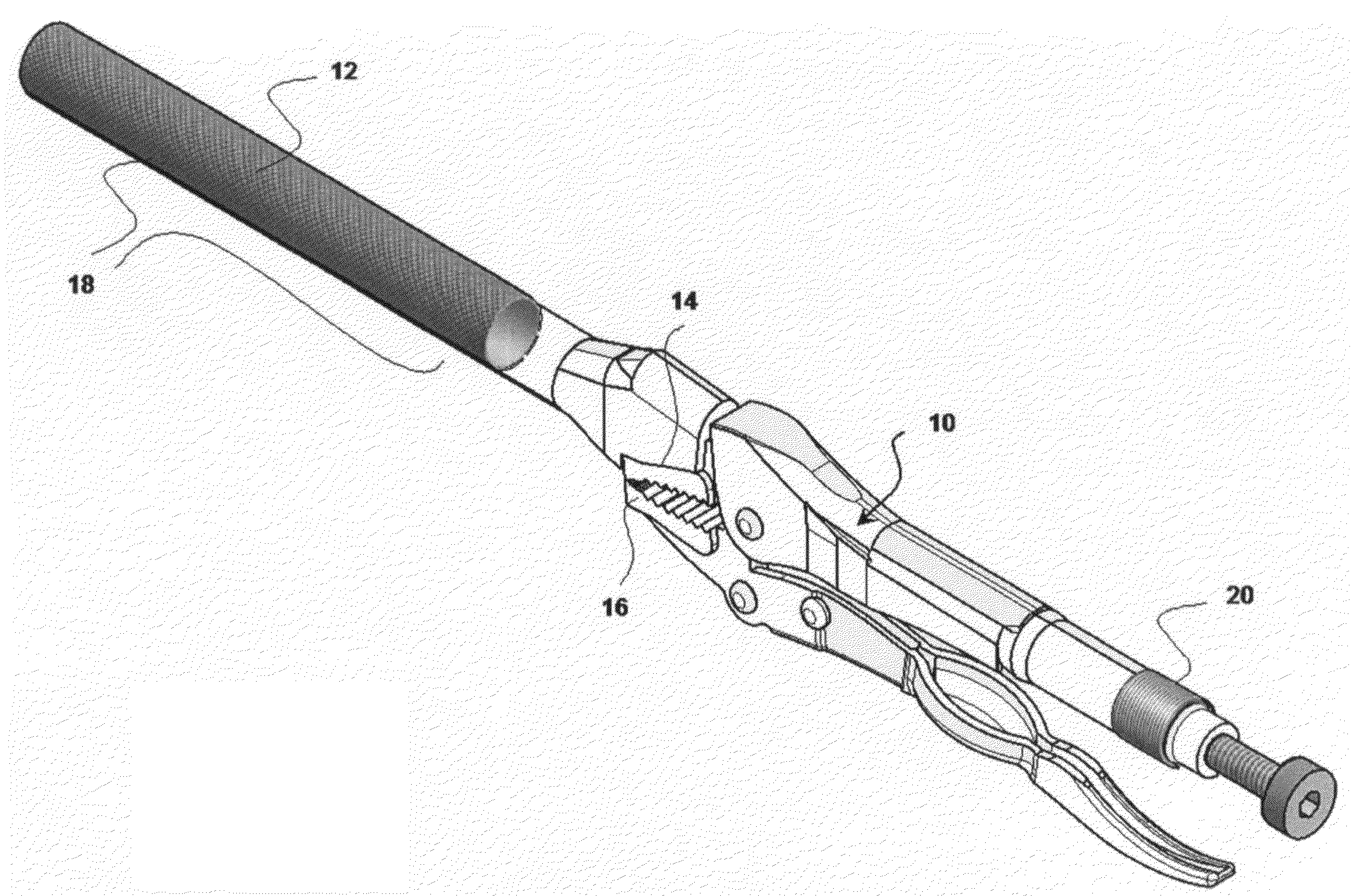
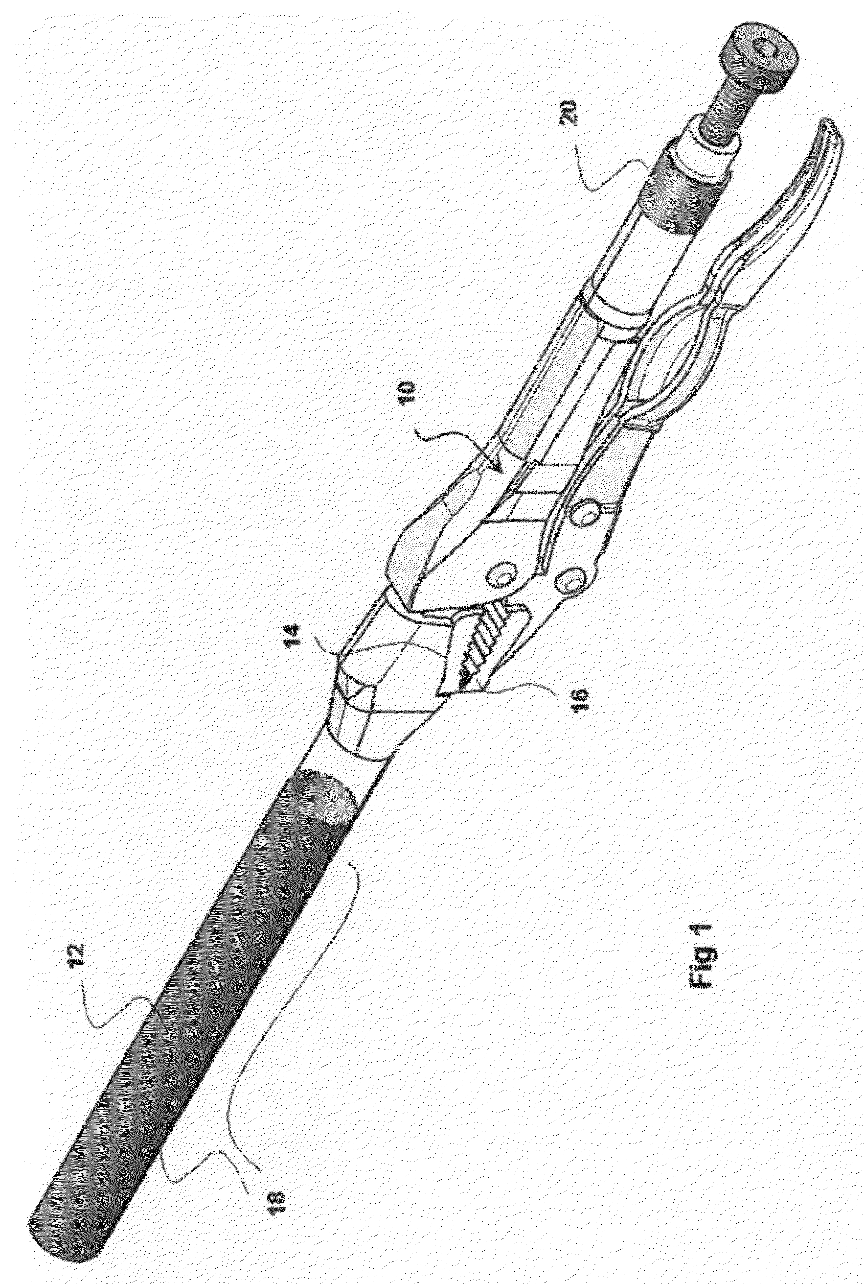
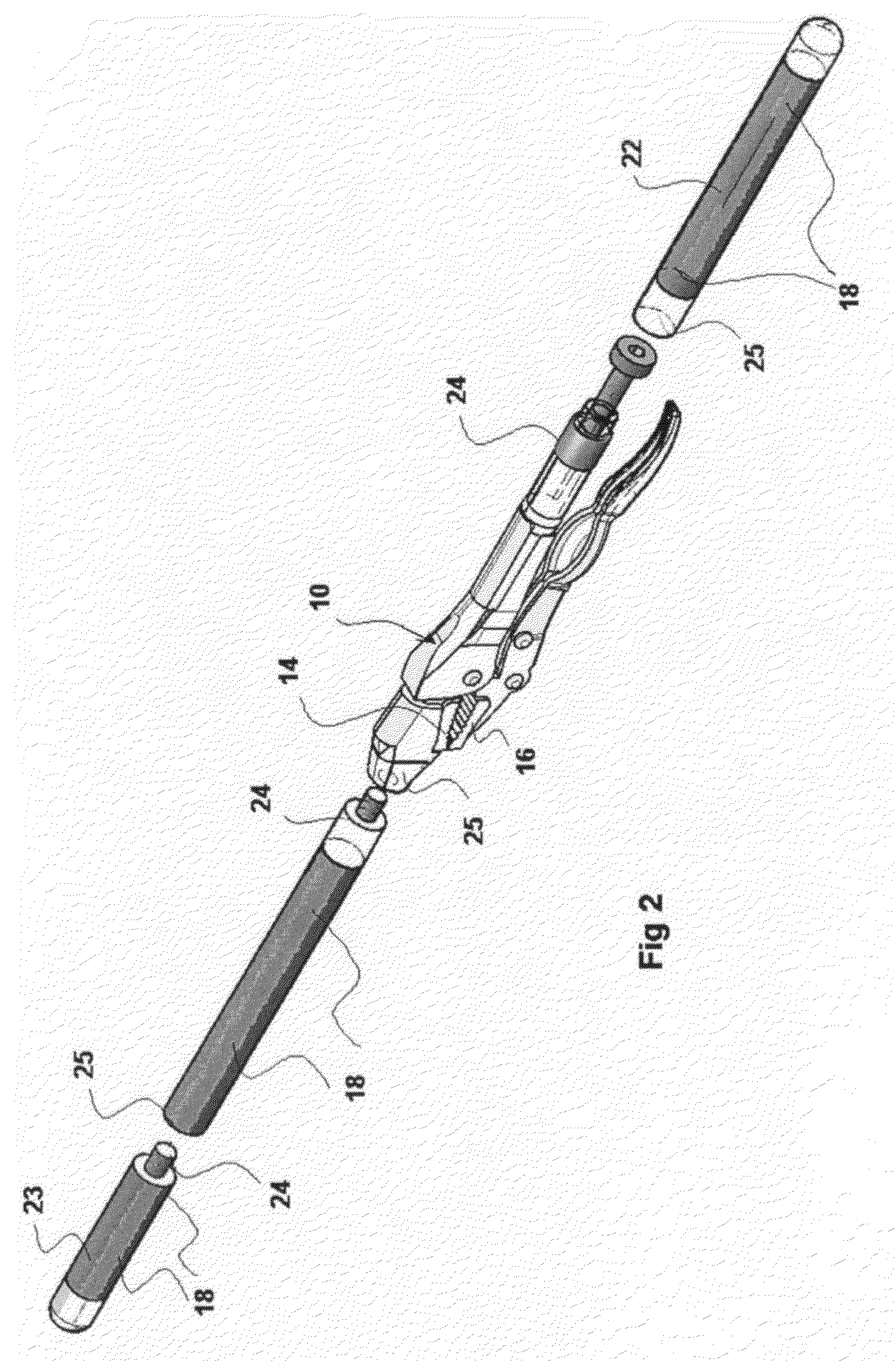
[0026]One embodiment of the locking pliers with opposing handle is illustrated in FIG. 1, while FIG. 2 illustrates a second embodiment of the invention. FIG. 1 shows the locking pliers 10, a first handle 20, an upper jaw 14, and a lower jaw 16. In accordance with the invention, upper jaw 14 is extended opposite the first handle 20 to form an opposing handle 12, approximately the same length, size and shape as the first handle 20. The opposing handle 12 has optional grooves or gnurling 18 or added friction material to the surface to facilitate the user's grip. The opposing handle 12, including the optional grooves or gnurling 18, and the upper jaw 14 can be made out of one single piece, or they can be made separately and coupled to the upper jaw 14 by way of a threaded joint or other suitable joint or attachment. Optional grooves or gnurling 18 of the opposing handle 12 can be replaced by covering its surface with various friction materials, such as nylon, plastic, rubber, polyuretha...


PUM


Abstract

The present invention is a pair of locking pliers having an opposing handle extending from the upper jaw or lower jaw of the locking pliers, generally parallel to, and roughly the same length and shape as, the first handle. A user can simultaneously place one hand on the first handle and the other hand on the opposing handle so that there is one handle on each side of the workpiece, allowing the user to apply more rotational force to the workpiece. The invention allows the user to apply pressure and torque more evenly to keep unstable work objects from moving, when not securely fixed. When space around the workpiece compromises the user's reach, the opposing handle provides and additional opportunity to rotate the workpiece. A second embodiment of the invention provides an optional, detachable handle extension securely attached to the upper jaw and / or an optional and detachable handle extension that can be securely attached to first handle of the locking pliers. The invention can also be applied to other similar hand tools such as adjustable pliers, wrenches, socket wrenches, pipe wrenches, or other tools.

Description

RELATED APPLICATIONS[0001]This application claims priority based on the Provisional Patent Application 61 / 001,151 filed on Oct. 31, 2007.BACKGROUND OF THE INVENTION[0002]1. Field of the Invention[0003]This invention relates to hand tools, and more specifically to a pair of locking pliers with an improved way for the user to grasp it.[0004]Locking pliers typically consist of a pair of pliers with the handles to be the continuation of the upper and lower jaws of the pliers.[0005]This invention provides an additional handle, extending from the upper jaw of the locking pliers so that the user can apply additional rotating force by grasping and rotating the pliers with both hands using two opposing handles instead of one.[0006]2. Brief Description of the Prior Art[0007]Locking pliers typically consist mainly of pliers with the handles to be the continuation of the upper and lower jaws of the pliers. U.S. Pat. No. 6,941,844 to Hile, and U.S. Pat. No. 6,857,342 to Wang are two examples of ...

Claims


Application Information

Patent Timeline
IPC IPC(8): B25B7/00
CPCB25B7/00B25G1/005B25B7/18B25B7/123
Inventor KAMMERMEIER, PAUL
Owner KAMMERMEIER PAUL
Why Eureka
Try Eureka