Liquid droplet discharging head, and liquid droplet discharging apparatus

a technology of liquid droplets and discharging heads, which is applied in printing and other directions, can solve the problems of hindering the accurate landing of liquid droplets on target positions, difficult to allow liquid droplets to accurately land on target positions, and insufficient stability of straight flight, so as to facilitate the landing of liquid droplets, facilitate the rotation of force, and high quality

Inactive Publication Date: 2007-09-20
SEIKO EPSON CORP
View PDF4 Cites 15 Cited by
  • Summary
  • Abstract
  • Description
  • Claims
  • Application Information

AI Technical Summary

Benefits of technology

[0008]An advantage of the present invention is to provide a liquid droplet discharging head that allows production of high-quality drawings even with highly miniaturized liquid droplets, a manufacturing method thereof, a liquid droplet discharging apparatus and a manufacturing method thereof. Another advantage of the invention is to allow production of high-quality drawings regardless of subtle diversions in a direction of a nozzle.
[0009]A liquid droplet discharging head according to a first aspect of the invention includes a substrate, a pressure chamber connected to the substrate, a penetrating portion formed in the substrate to discharge a liquid droplet and a plurality of liquid droplet guiding portions formed at the penetrating portion of the substrate to guide the liquid droplet, in which each of the liquid droplet guiding portions extends with a curvature in an discharging direction of the liquid droplet.
[0010]In the liquid droplet discharging head according to the first aspect, the liquid droplet guiding portions are formed at the penetrating portion and extend with the curvature in the discharging direction of the liquid droplet. This makes it easier to apply a rotational force to the liquid droplet, so that the liquid droplet can easily be focused to a center of the penetrating portion. Then, the liquid droplet discharged from the penetrating portion is hardly influenced by air resistance and will fly straight in an air. Consequently, the structure facilitates the liquid droplet to land on a target position accurately. Therefore, the liquid droplet discharging head allows improvement in landing position accuracy of liquid droplets.
[0011]In addition, preferably, the liquid droplet discharging head according to the first aspect further includes a plurality of pointed end portions provided on a surface of the penetrating portion in a direction intersecting with the discharging direction of the liquid droplet, the pointed end portions being included in the liquid droplet guiding portions.
[0012]In this manner, the plurality of pointed end portions are formed at the liquid droplet guiding portions on the surface of the penetrating portion and are positioned in the direction intersecting with the discharging direction of the liquid droplet. An intersection of the liquid droplet with each of the pointed end portions makes it easier to apply a rotational force to the liquid droplet. This makes it easier for the liquid droplet to be focused to the center of the penetrating portion. Accordingly, the liquid droplet discharged from the penetrating portion will fly straight in the air, thereby landing on the target position accurately. Therefore, the liquid droplet discharging head allows improvement in the landing position accuracy.
[0013]In addition, preferably, in the liquid droplet discharging head according to the first aspect, a surface wettability with respect to the liquid droplet is different between the liquid droplet guiding portions and a region other than the guiding portions on the penetrating portion.

Problems solved by technology

In the liquid droplet discharging head disclosed in the above example, however, along with further miniaturization of liquid droplets, the straight flight stability thereof has not been sufficiently maintained due to air resistance.
Accordingly, it has been difficult to allow liquid droplets to accurately land on target positions thereof.
On the other hand, further miniaturization thereof hinders their accurate landing on target positions.
As a result, a subtle diversion in the nozzle directions has caused a failure in the accurate landing of liquid droplets on target positions.
Therefore, the above problem has hindered the production of high-quality drawings.

Method used


Image

  • Liquid droplet discharging head, and liquid droplet discharging apparatus
  • Liquid droplet discharging head, and liquid droplet discharging apparatus
  • Liquid droplet discharging head, and liquid droplet discharging apparatus

Examples


first embodiment

[0118]A first embodiment of the invention describes a liquid droplet discharging head in which a nozzle as a penetrating portion includes a spiral narrow groove used as a liquid droplet guiding portion. The liquid droplet guiding portion means a physical structure such as a groove formed by carving a surface of the penetrating portion formed in a substrate or a protruded portion formed on the substrate, with a chemical structure such as lyophilic and lyophobic regions formed on the surface of the penetrating portion. Any of the structures can serves to help a liquid droplet pass through the penetrating portion.

[0119]First, a description will be given of a structure of the liquid droplet discharging head incorporated in a liquid droplet discharging apparatus, according to exemplary embodiments of the invention.

[0120]FIGS. 12A and 12B partially show a main part of the liquid droplet discharging head. FIG. 12 is a schematic perspective view of the main part thereof and FIG. 12B is a sc...

second embodiment

[0146]A second embodiment of the invention describes a liquid droplet discharging head including a linear groove formed at a nozzle section of the nozzle plate. The linear groove is formed on the first penetrating portion.

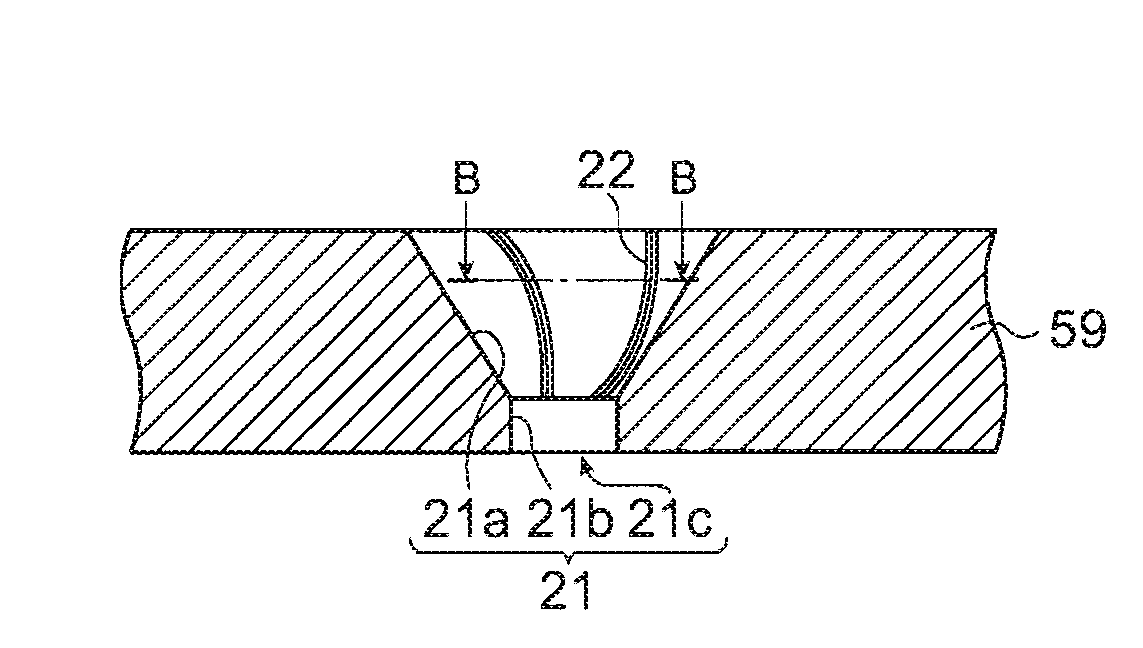
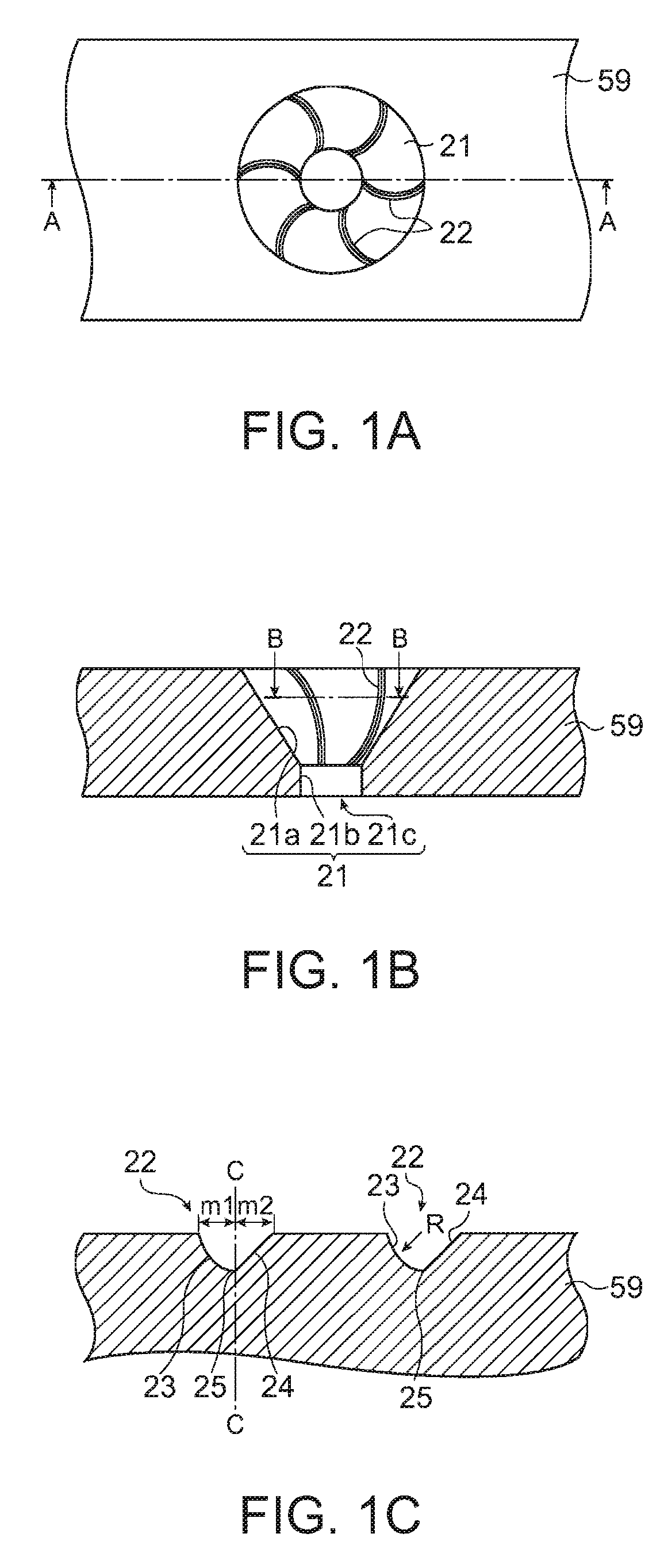
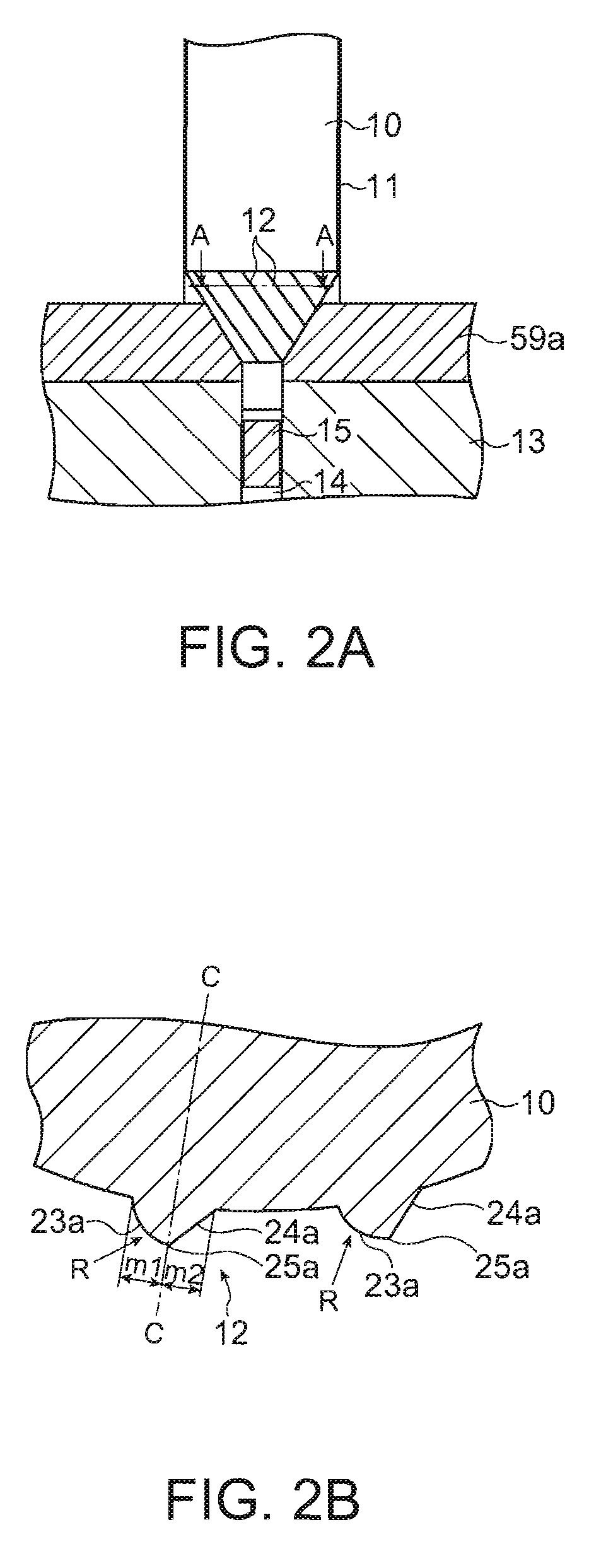
[0147]FIGS. 3A to 3C schematically show an example of the nozzle plate included in the liquid droplet discharging head according to the second embodiment. FIG. 3A is a plan view of the example thereof, FIG. 3B is a sectional view of the example thereof taken along a line A-A of FIG. 3A. FIG. 3C is a sectional view of the example thereof taken along a line B-B of FIG. 3B. FIGS. 4A and 4B illustrate a method for manufacturing the nozzle plate included in the liquid droplet discharging head. FIG. 4A is a schematic view of the nozzle plate and FIG. 4B is a sectional view thereof taken along a line A-A of FIG. 4B. Referring to FIGS. 3A to 3C and 4A and 4B, a description will now be given of the nozzle plate included in the liquid droplet discharging head according to th...

third embodiment

[0159]A third embodiment of the invention describes a liquid droplet discharging head having patterns with different wettabilities at the nozzle section of the nozzle plate. Those patterns having different wettabilities are formed at the first penetrating portion.

[0160]FIGS. 5A and 5B schematically show an example of the nozzle plate included in the liquid droplet discharging head according to the third embodiment. FIG. 5A is a plan view of the example thereof and FIG. 5B is a sectional view taken along a line A-A of FIG. 5A. FIGS. 6A and 6B illustrate a method for manufacturing the nozzle plate included in the liquid droplet discharging head. FIG. 6A is a schematic view of a photomask and FIG. 6B shows a state in which the photomask is placed on a nozzle plate material. FIG. 7 shows a flowchart of processes performed in the manufacturing method of the nozzle plate included in the liquid droplet discharging head. Referring to FIGS. 5A to 7, a description will be given of the nozzle ...


PUM


Abstract

A liquid droplet discharging head includes: a substrate; a pressure chamber connected to the substrate; a penetrating portion formed in the substrate to discharge a liquid droplet; and a plurality of liquid droplet guiding portions formed at the penetrating portion of the substrate to guide the liquid droplet, in which each of the liquid droplet guiding portions extends with a curvature in an discharging direction of the liquid droplet.

Description

BACKGROUND[0001]1. Technical Field[0002]Several aspects of the present invention relate to a liquid droplet discharging head, a method for manufacturing the same, a liquid droplet discharging apparatus and a method for manufacturing the same.[0003]2. Related Art[0004]Related art discloses that a method for drawing a minute pattern such as a metal wiring by using a liquid droplet discharging technique such as an inkjet printer or the like and an application example of the technique.[0005]For example, JP-A-05-193144 provides a structure of a liquid droplet discharging head. In the structure thereof, a nozzle section is formed so as to have a conical shape on an discharging side of the liquid droplet discharging head. This improves a stability of straight flight of a liquid droplet and reduces a variation in the amount of a liquid droplet discharged from each nozzle. In addition, there is provided a method for manufacturing the nozzle section of the liquid droplet discharging head. The...

Claims


Application Information

Patent Timeline
Patent Type & Authority Applications(United States)
IPC IPC(8): B41J2/16
CPCB41J2/1433B41J2/1606B41J2002/14475B41J2/1631B41J2/1632B41J2/162B41J2/14
Inventor SHIMURA, YASUTOUSUI, TAKAHIROSAKAI, SHINRI
Owner SEIKO EPSON CORP
Why Eureka
Try Eureka