Motor

Inactive Publication Date: 2009-05-21
NIDEC SANKYO CORP
View PDF6 Cites 6 Cited by
  • Summary
  • Abstract
  • Description
  • Claims
  • Application Information

AI Technical Summary

Benefits of technology

[0008]In view of the problems described above, at least an embodiment of the present invention may advantageously provide a motor in which an u

Problems solved by technology

However, there are the following problems in the mounting structure described in the above-mentioned Patent Reference.
Firstly, in the structure described in the Patent Reference, in order to fix the urging member at a predetermined position, a tip end holding part for holding a tip end side of the rotation shaft is required to form a recessed part to which a pawl part formed in the urging member is fitted and thus machining on the tip end holding

Method used


Image

  • Motor
  • Motor
  • Motor

Examples


Example

[0028]A motor in accordance with an embodiment of the present invention will be described in detail below with reference to the accompanying drawings.

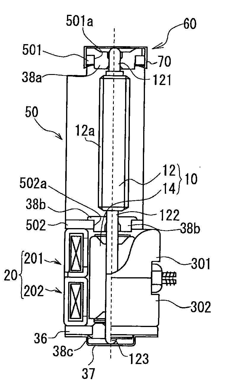
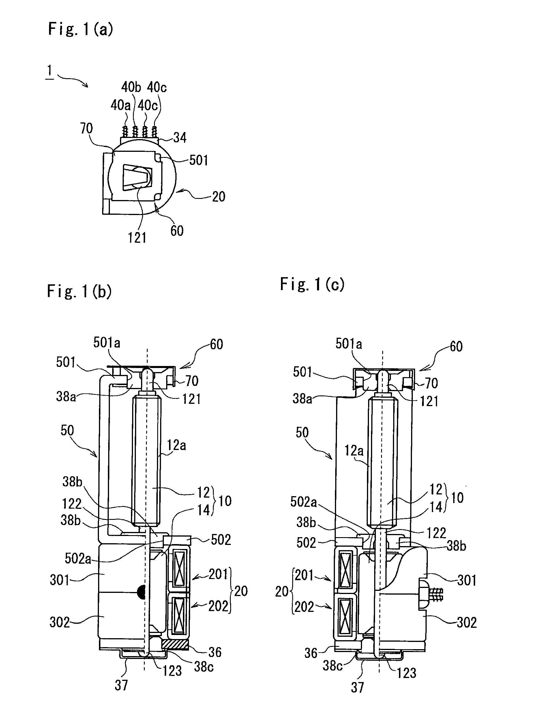
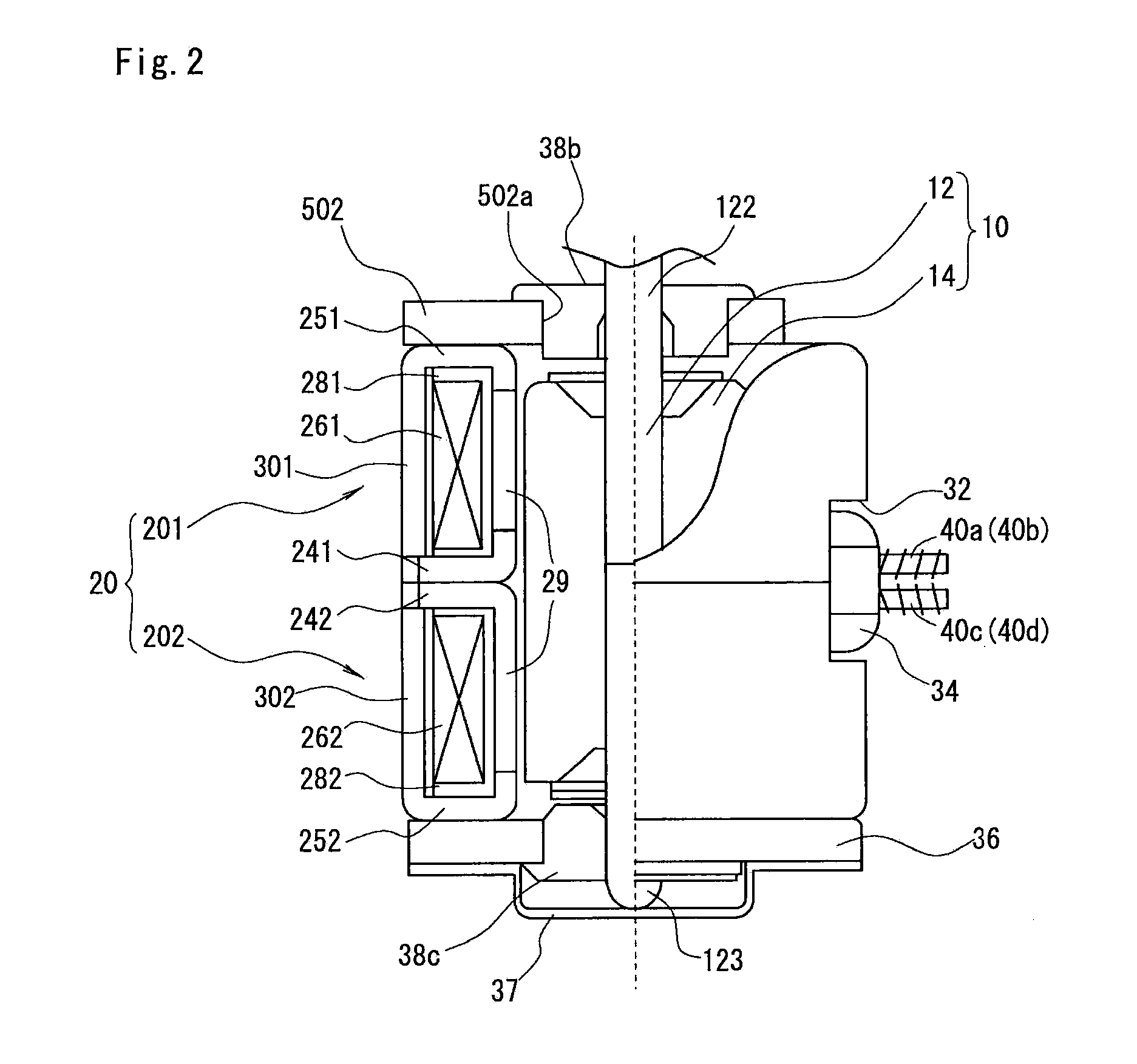
[0029]FIGS. 1(a) through 1(c) and FIG. 2 are explanatory views showing a structure of a motor 1 in accordance with an embodiment of the present invention. FIG. 1(a) is a side view of the motor 1 in its short side direction which is viewed from an output side, FIG. 1(b) is a side view (partly cross-sectional view) of the motor 1 in its longitudinal direction, and FIG. 1(c) is a top plan view (partly cross-sectional view) of the motor 1. FIG. 2 is an enlarged view showing a rotor 10 and a stator 20 (main body of motor) shown in FIG. 1(c).

[0030]The motor 1 in accordance with an embodiment of the present embodiment includes a rotor 10 provided with a rotation shaft 12, a stator 20 disposed on an outer peripheral side of the rotor 10, a frame 50 which is fixed to the stator 20 and formed in a U-shape in cross section, and an urging member 7...


PUM


Abstract

A motor may include a rotor provided with a rotation shaft, a stator, a frame fixed to the stator and provided with a bearing part that rotatably supports an output side of the rotation shaft, and an urging member mounted on the bearing part for urging the rotation shaft. The bearing part may include a bearing, formed with a protruded part protruded from a flat plate part of the frame. The urging member may include a bottom face part provided with a spring part for urging the rotation shaft, a pair of side plate parts bent from side edge parts of the bottom face part, and a pair of hook parts bent on inner sides from the pair of the side plate parts to be engaged with the protruded part. The urging member is mounted on the bearing part such that the hook parts are engaged with the protruded part.

Description

CROSS REFERENCE TO RELATED APPLICATION[0001]The present invention claims priority under 35 U.S.C. §119 to Japanese Application No. 2007-296582 filed Nov. 15, 2007 the entire contents of which are incorporated herein by reference.FIELD OF THE INVENTION[0002]At least an embodiment of the present invention may relate to a motor. More specifically, at least an embodiment of the present invention may relate to a motor which is provided with an urging member for urging a bearing that supports a rotation shaft of the motor in a rotation shaft direction.BACKGROUND OF THE INVENTION[0003]A rotation shaft of a motor which is supported by bearings is commonly structured such that its shaft end is urged in an axial direction by an urging member such as a plate spring. According to this structure, rattling, inclination or the like of the rotation shaft which is supported by the bearings are prevented.[0004]Various mounting structures of the urging member have been proposed. For example, in Japane...

Claims


Application Information

Patent Timeline
IPC IPC(8): H02K7/08
CPCH02K5/1672H02K7/081
Inventor KASAI, SHIGERU
Owner NIDEC SANKYO CORP
Why Eureka
Try Eureka