Electronic Circuits for Driving Series Connected Light Emitting Diode Strings

a technology of light-emitting diodes and electrical circuits, applied in the direction of electric variable regulation, process and machine control, instruments, etc., can solve the problem that the switch regulator would generate unnecessarily high power dissipation, and achieve the effect of reducing power dissipation

Active Publication Date: 2009-05-21
ALLEGRO MICROSYSTEMS INC
View PDF43 Cites 166 Cited by
  • Summary
  • Abstract
  • Description
  • Claims
  • Application Information

AI Technical Summary

Benefits of technology

[0018]The above-described circuits and method provide a controllable DC-DC converter to drive a plurality of series connected light emitting diode strings. The controllable DC-DC converter is controlled in such a way as to provide just enoug...

Problems solved by technology

While it is possible to provide a fixed voltage switching regulator that can supply enough voltage for all possible series strings of LEDs, su...

Method used


Image

  • Electronic Circuits for Driving Series Connected Light Emitting Diode Strings
  • Electronic Circuits for Driving Series Connected Light Emitting Diode Strings
  • Electronic Circuits for Driving Series Connected Light Emitting Diode Strings

Examples


Embodiment Construction

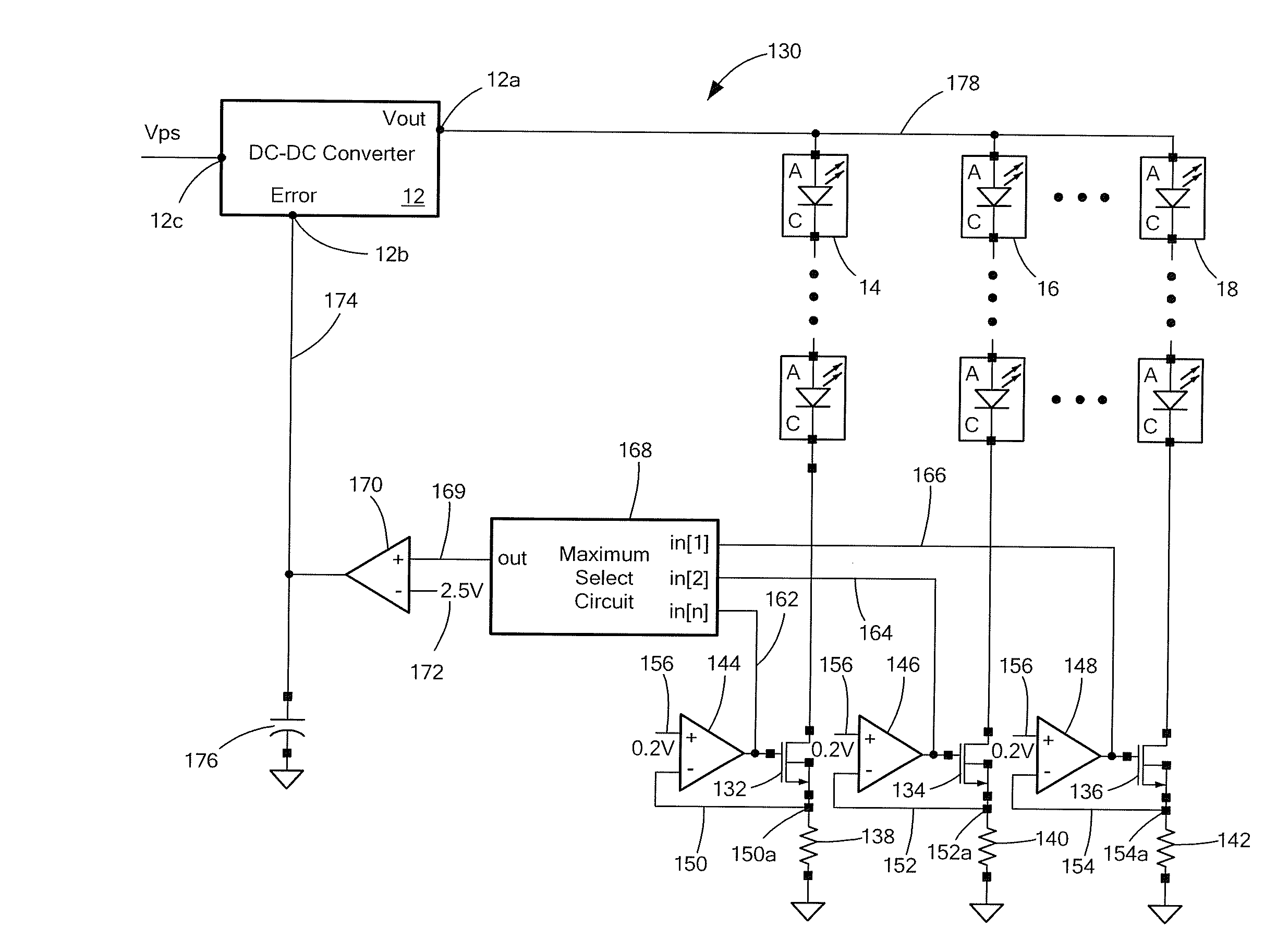
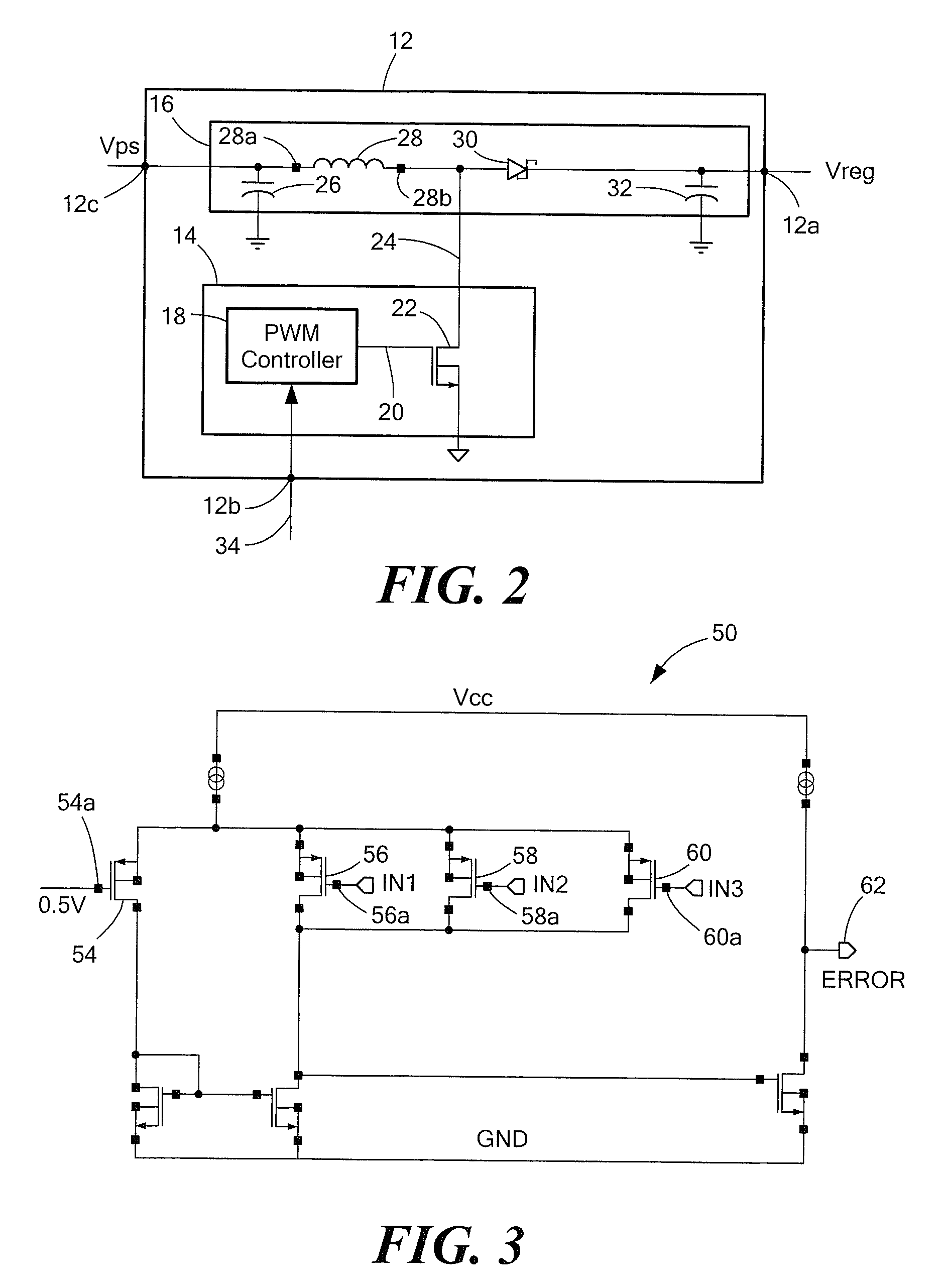
[0029]Before describing the present invention, some introductory concepts and terminology are explained. As used herein, the term “boost switching regulator” is used to describe a known type of switching regulator that provides an output voltage higher than an input voltage to the boost switching regulator. While a certain particular circuit topology of boost switching regulator is shown herein, it should be understood that boost switching regulators have a variety of circuit configurations. As used herein, the term “buck switching regulator” is used to describe a known type of switching regulator that provides an output voltage lower than an input voltage to the buck switching regulator. It should be understood that there are still other forms of switching regulators other than a boost switching regulator and other than a buck switching regulator, and this invention is not limited to any one type.

[0030]DC-DC converters are described herein. The described DC-DC converters can be any...


PUM


Abstract

Electronic circuits provide an error signal to control a regulated output voltage signal generated by a controllable DC-DC converter for driving one or more series connected strings of light emitting diodes.

Description

CROSS REFERENCE TO RELATED APPLICATIONS[0001]This application claims the benefit under 35 U.S.C. §119(e) of U.S. Provisional Application No. 60 / 988,520 filed Nov. 16, 2007, which application is incorporated herein by reference in its entirety.STATEMENT REGARDING FEDERALLY SPONSORED RESEARCH[0002]Not Applicable.FIELD OF THE INVENTION[0003]This invention relates generally to electronic circuits and, more particularly, to electronic circuits used to drive a diode load, for example, a light emitting diode (LED) load.BACKGROUND OF THE INVENTION[0004]A variety of electronic circuits are used to drive diode loads and, more particularly, to control electrical current through strings of series connected light-emitting diodes (LEDs), which, in some embodiments, form an LED display, or, more particularly, a backlight for a display, for example, a liquid crystal display (LCD). It is known that individual LEDs have a variation in forward voltage drop from unit to unit. Therefore, the strings of ...

Claims


Application Information

Patent Timeline
IPC IPC(8): H05B41/16H05B44/00
CPCH05B33/0815H05B33/0818H05B33/0827G09G3/3413G09G3/342G09G2320/064G09G2330/021H05B45/46H05B45/347Y02B20/30H05B45/3725H05B45/50H05B45/37
Inventor SZCZESZYNSKI, GREGORYALNAHAS, BASSEMMANGTANI, VIJAY
Owner ALLEGRO MICROSYSTEMS INC
Why Eureka
Try Eureka