
Ink jet recording head, ink jet cartridge with ink jet recording head, and ink jet recording apparatus

a technology recording head, which is applied in the field of ink jet recording head, ink jet recording head with ink jet recording apparatus, etc., can solve the problems of unnecessarily reducing the speed at which an ink jet recording head prints a color image, the difficulty of seeing the individual dots formed by the ink droplets of the ink jet recording head, and the increase of the number of resultant satellite ink droplets

Inactive Publication Date: 2009-05-21
CANON KK
View PDF16 Cites 14 Cited by
  • Summary
  • Abstract
  • Description
  • Claims
  • Application Information

AI Technical Summary

Benefits of technology

The present invention provides an ink jet recording head that can eject smaller ink droplets to create higher quality images faster. The head has three nozzle array groups, with the second group having smaller ejection outlets than the first group. The nozzle arrays are arranged in a specific order to prevent non-uniform image quality. The invention also includes a third nozzle array in each adjacent group, with smaller ejection outlets to prevent non-uniformity. Overall, the invention allows for faster and higher quality image formation.

Problems solved by technology

In order to achieve a high level of image quality which is as high as that achievable by silver salt photography, with the use of an ink jet recording, it is necessary to reduce the ink jet recording head in ink droplet size, to a degree that it is difficult to see the individual dots formed by the ink droplets from the ink jet recording head.
However, it unnecessarily reduces the speed at which an ink jet recording head prints a color image which does not need to be printed in high resolution.
In other words, it is undesirable from the standpoint of high speed printing.
Another cause is that the smaller the size of a primary ink droplet, the greater the number of the resultant satellite ink droplets.
However, this method directly increases the length of time it takes for an ink jet recording head to complete an image, being therefore undesirable from the standpoint of forming a high quality image at a high speed.

Method used


Image

  • Ink jet recording head, ink jet cartridge with ink jet recording head, and ink jet recording apparatus
  • Ink jet recording head, ink jet cartridge with ink jet recording head, and ink jet recording apparatus
  • Ink jet recording head, ink jet cartridge with ink jet recording head, and ink jet recording apparatus

Examples


embodiment 1

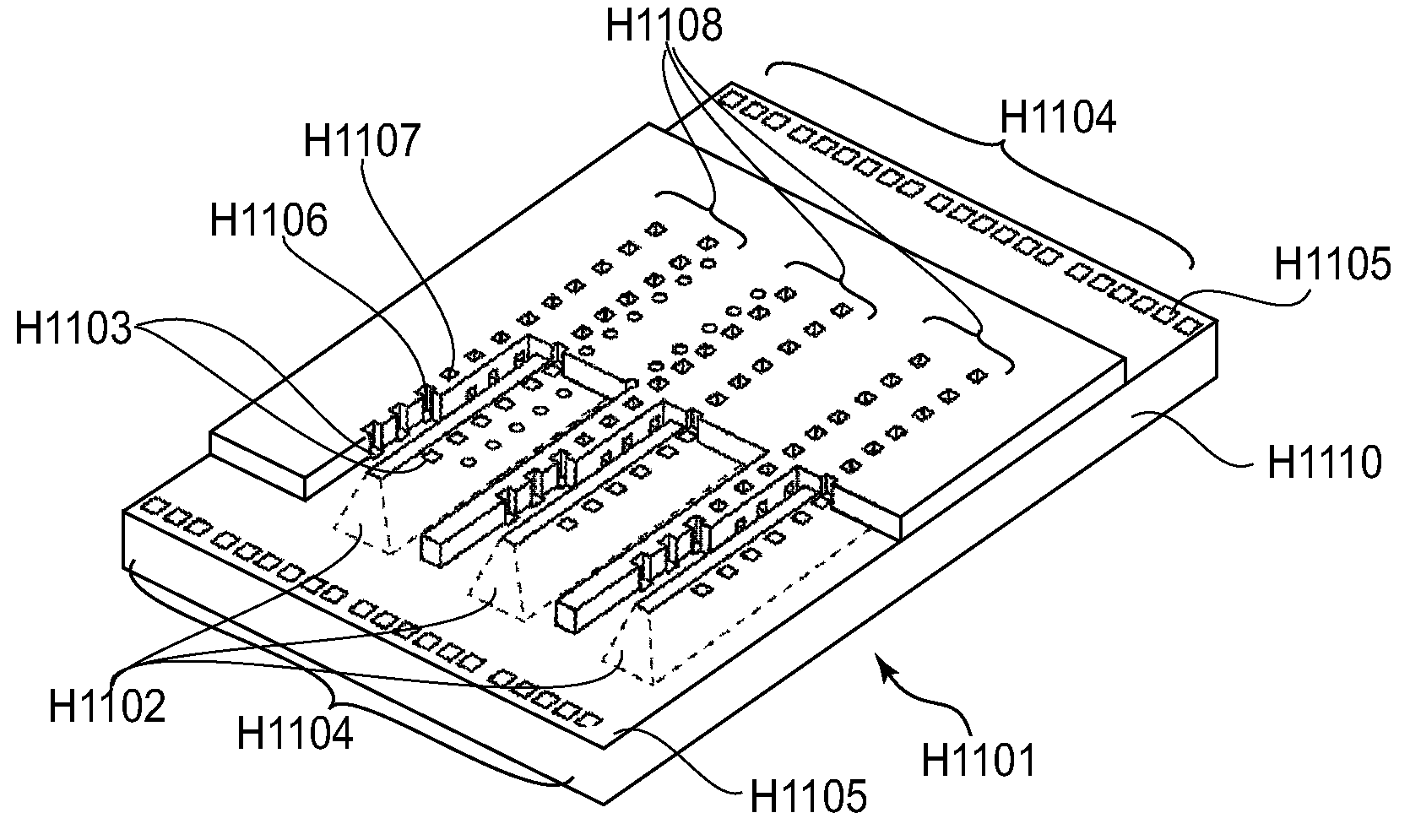
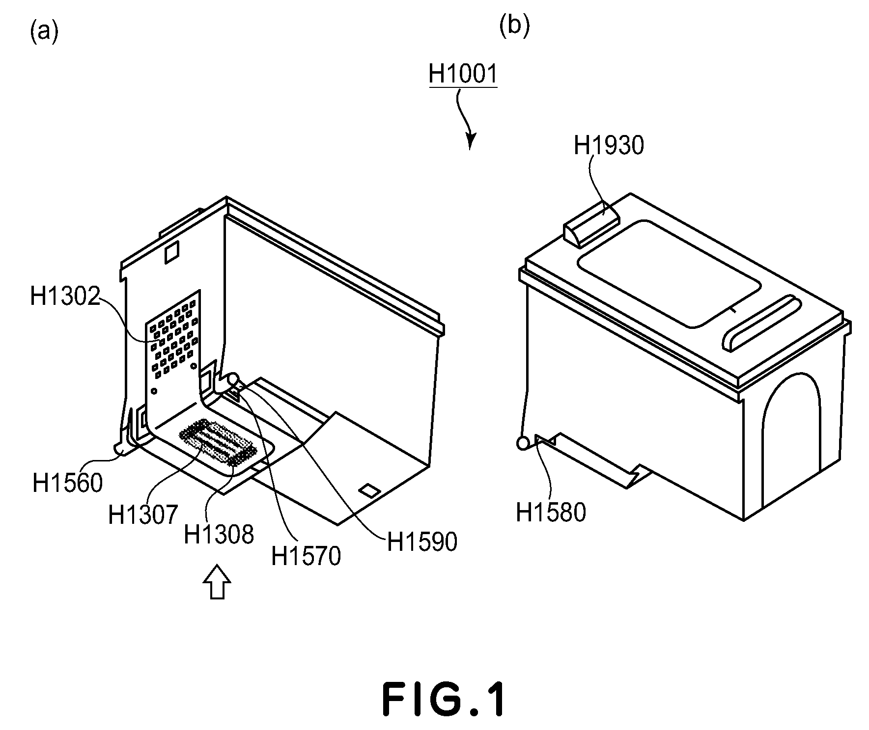
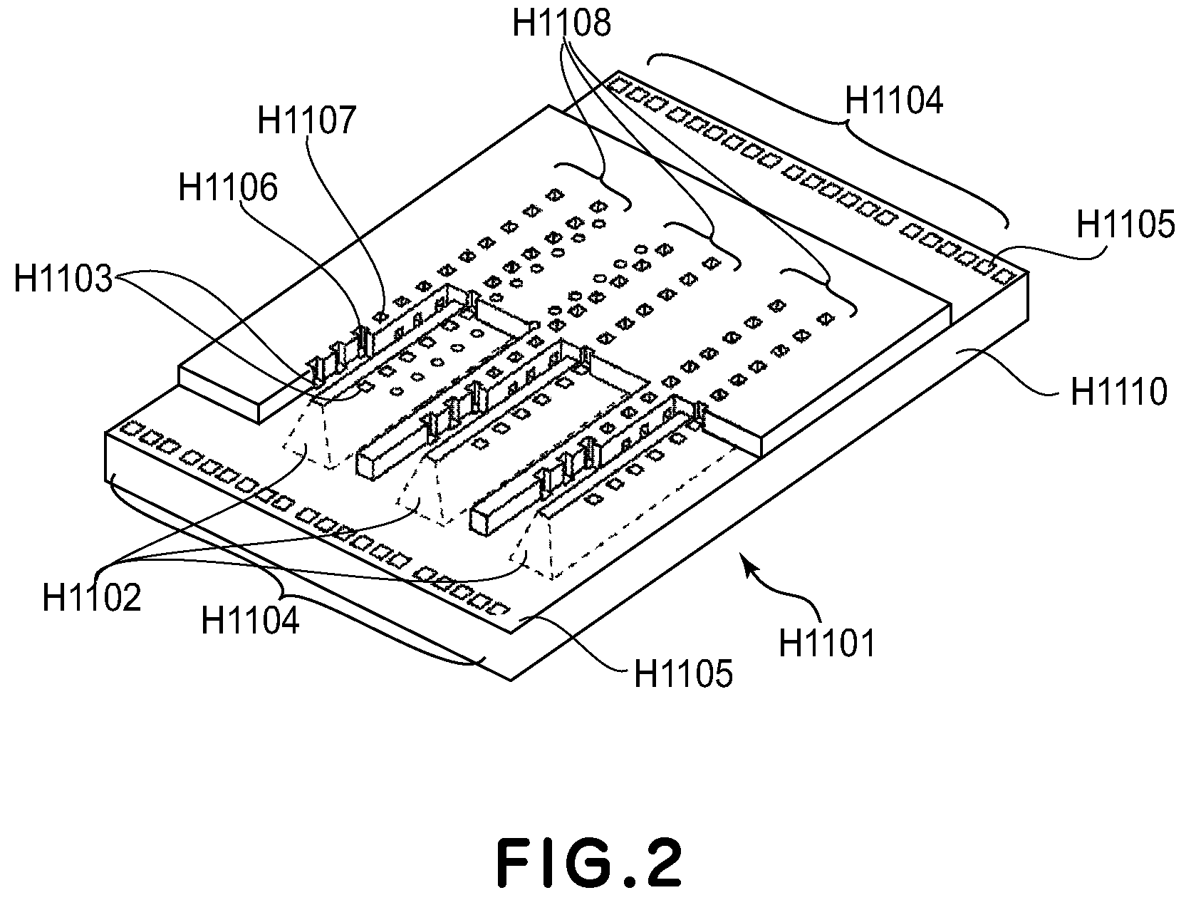
[0051]FIG. 6 is a schematic drawing of the recording element H1101 of the above described ink jet cartridge H1001 in the first embodiment of the present invention, showing the arrangement of the ink ejecting openings (nozzle arrangement) as observed from the direction indicated by an arrow mark in FIG. 1(a).

[0052]The ink jet recording head in accordance with the present invention was made based on the above described referential example of an ink jet recording head, and its object is to record an image at a higher level of resolution and a higher level of precision than those at which the referential ink jet recording head can record an image. One of the methods for accomplishing this object is to provide an ink jet recording apparatus with not only large and small nozzle sets, such as those of the referential ink jet recording head, but also, a set or sets of nozzles which are smaller in size than the small nozzles of the referential ink jet recording head, and therefore, are capab...

embodiment 2

[0062]FIG. 7 is a schematic drawing of the recording element H1101 of the ink cartridge H1001 in this embodiment, as seen from the same direction as the one indicated by an arrow mark in FIG. 1(a), showing the nozzle arrangement thereof. The ink jet recording head in this embodiment has one more ink ejecting section than the ink jet recording head in the above described first embodiment. That is, the ink jet recording head in this embodiment has first-fourth ink ejecting sections, and a total of ten ink ejecting opening sets made up of multiple ink ejecting openings described above. More specifically, the first ink ejecting section has a first large nozzle set 501, a first small nozzle set 502, and a first micro-nozzle set 503, and the second ink ejecting section has a second large nozzle set 504, a second small nozzle set 505, and a second micro-nozzle set 506. The third ink ejecting section has a third large nozzle set 507 and a third small nozzle set 508, and the fourth ink eject...


PUM


Abstract

An ink jet recording head includes at least three nozzle array groups; each of the nozzle array group including, a first nozzle array including a plurality of ejection outlets for ejecting ink, and a second nozzle array including a plurality of ejection outlets for ejecting the ink, the second nozzle array being disposed adjacent to the first nozzle array with an ink supply port for supplying the ink interposed therebetween, wherein an opening area of the ejection outlets of second nozzle array is smaller than an opening area of the ejection outlets of first nozzle array, wherein the nozzle array groups eject three different kinds of inks, respectively, when the ink jet recording head moves relative to a recording material, wherein the nozzle arrays of adjacent ones of the nozzle array group are arranged in the order of the first nozzle array of one of the adjacent nozzle array groups, the second nozzle array of the one of the adjacent nozzle array groups, the second nozzle array of the other one of the adjacent nozzle array groups, and the first nozzle array of the other one of the adjacent nozzle array groups; and the recording head further including a third nozzle array provided in each of the adjacent ones of the nozzle array groups, the third nozzle array including a plurality of ejection outlets for ejecting the ink, wherein an opening area of the ejection outlets of third nozzle array is smaller than an opening area of the ejection outlets of second nozzle array, wherein the third nozzle array being disposed in the same side as the second nozzle array with respect to the ink supply port, and wherein the nozzle array group which does not constitute the adjacent nozzle array groups is supplied with the ink having a highest lightness among the three kinds of inks.

Description

TECHNICAL FIELD[0001]The present invention relates to an ink jet recording head, which records an image by ejecting liquid such as ink. It also relates to an ink jet cartridge equipped with an ink jet recording head, and a recording apparatus equipped with an ink jet recording head.BACKGROUND ART[0002]In order to achieve a high level of image quality which is as high as that achievable by silver salt photography, with the use of an ink jet recording, it is necessary to reduce the ink jet recording head in ink droplet size, to a degree that it is difficult to see the individual dots formed by the ink droplets from the ink jet recording head. Thus, various ink jet recording heads have been devised, which are roughly 5 pl (pico liter: 10−12 liter) in ink droplet size, 40-50 μm in dot size, and 600×1200-1200×1200 dpi in resolution. Some of them have been put to practical use.[0003]However, in order to satisfy users who want to further reduce an ink jet recording head in the graininess o...

Claims


Application Information

Patent Timeline
Patent Type & Authority Applications(United States)
IPC IPC(8): B41J2/145
CPCB41J2/1433B41J2002/14475B41J2/2125B41J2/145B41J2/01B41J2/05B41J2/1404B41J2/14137B41J2/17523B41J2/205B41J2/2135
Inventor NAGATA, SHINGOTSUKUDA, KEIICHIRO
Owner CANON KK
Learn More