LED collimator having spline surfaces and related methods

a collimator and spline surface technology, applied in the field of optical structures, can solve the problems of increasing beam divergence properties, affecting the performance of collimators, and only being able to adjust the size to a limited extent, so as to improve improve the effect of collimation and beam divergence properties and uniform light patterns

Inactive Publication Date: 2009-05-21
PHILIPS SOLID STATE LIGHTING SOLUTIONS
View PDF99 Cites 98 Cited by
  • Summary
  • Abstract
  • Description
  • Claims
  • Application Information

AI Technical Summary

Benefits of technology

[0009]Applicant herein has recognized and appreciated that one or more of the desirable characteristics of the collimator mentioned above can be realized without sacrificing performance in other areas by providing a collimator having one or more surfaces having a spline profile, such as a reflective spline surface, configured to account for angular errors resulting from the finite size of the light source. Thus, a lighting apparatus and collimator for an LED light source according to various implementations and embodiments of the present invention exhibit improved collimation and beam divergence properties, as well as a uniform light pattern. Furthermore, the collimator can be fabricated using off-the-shelf design software and relatively simple manufacturing techniques, thereby providing optimal reproducibility and high manufacturing yields.

Problems solved by technology

Furthermore, design factors relating to an LED light fixture in which one or more collimators may be employed often set constraints on the size of the collimator, so that the size can only be adjusted to a limited extent in order to improve (e.g., reduce) beam divergence.
Another drawback of conventional LED collimators is that some uncollimated light can escape at flange 124 or similar retaining structure, resulting in the formation of undesirable light rings in the light pattern.
However, such an approach may increase beam divergence properties.

Method used


Image

  • LED collimator having spline surfaces and related methods
  • LED collimator having spline surfaces and related methods
  • LED collimator having spline surfaces and related methods

Examples


Embodiment Construction

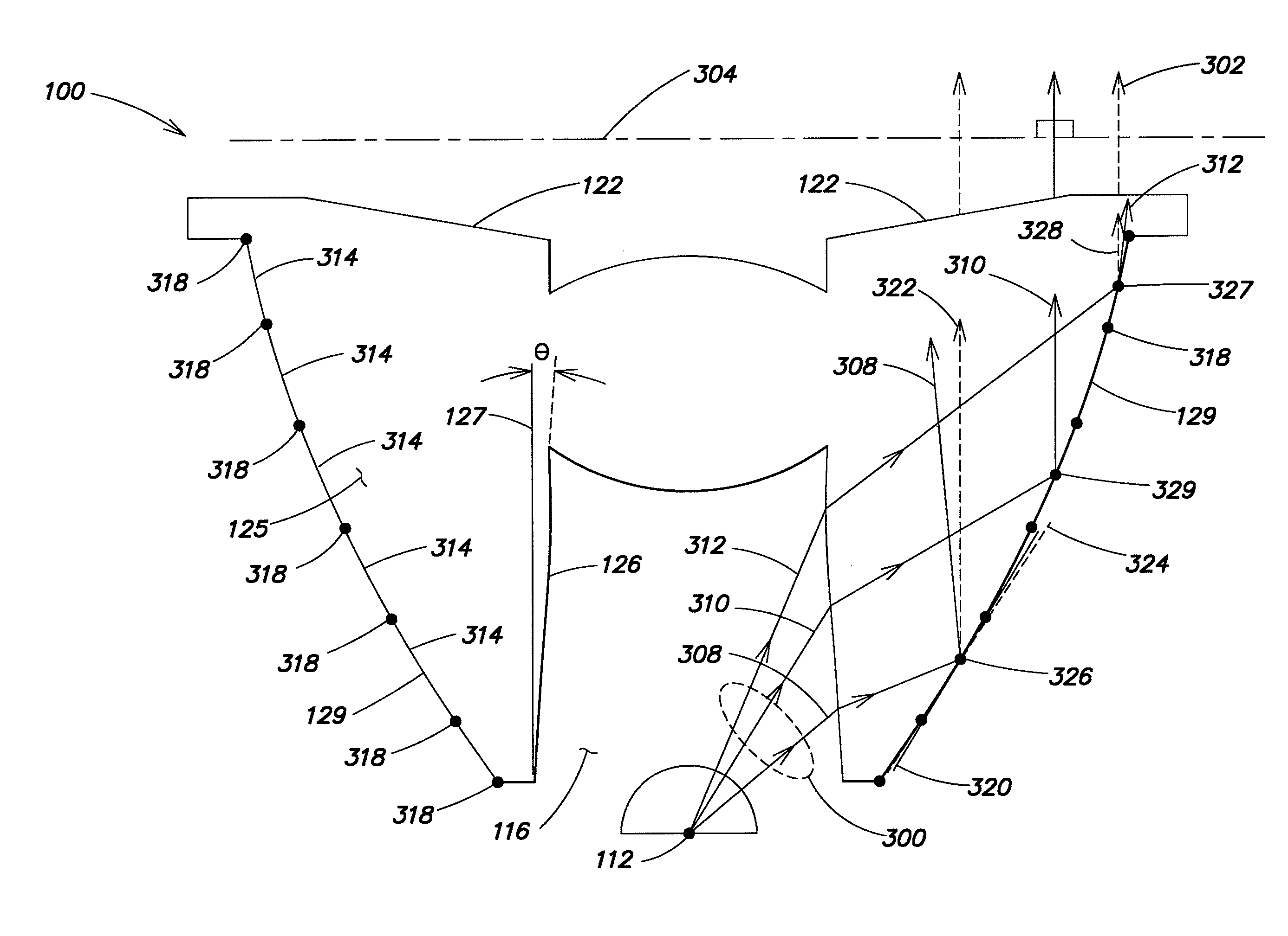
[0034]A collimator in accordance with the various embodiments and implementations of the invention is a fully-integrated, low-profile optical structure, which is easily manufactured in a highly reproducible manner. Its improved collimating functionalities are achieved without requiring additional hardware or space, enabling higher densities of LED light sources in a lighting apparatus employing one or more collimators according to the present invention. This, in turn, leads to improved light mixing properties and greater control of the light output of such apparatus and adds another degree of freedom or useful variable(s) to the system.

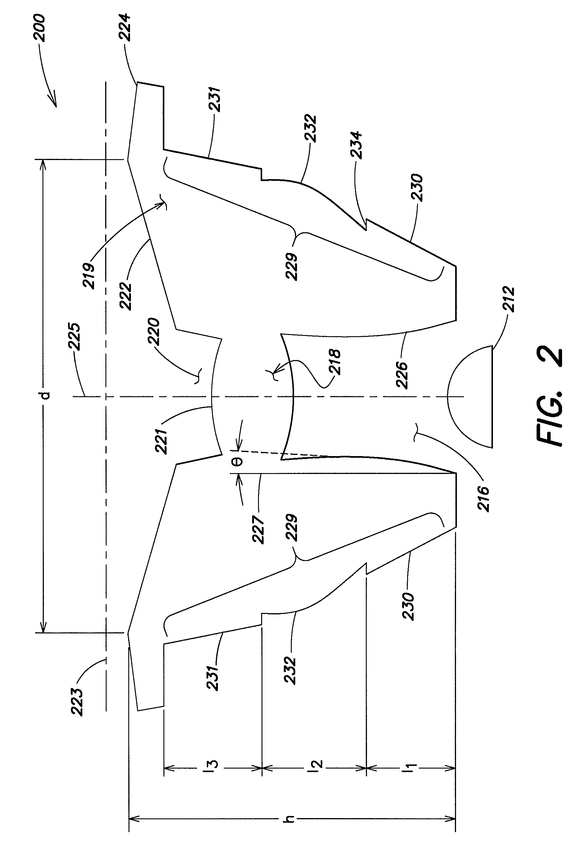
[0035]Referring to FIG. 2, a collimator 200 in accordance with various embodiments of the present invention is disposed to receive light emitted by an LED light source 212. In general, the light source and collimator provide collimated light for a lighting apparatus employing these elements. In one exemplary implementation, the collimator is generally...


PUM


Abstract

A TIR collimator for an LED light source includes a body portion having a reflective surface, wherein the reflective surface includes a plurality of segments. Respective segments of the reflective surface have corresponding cross-sectional profiles defined by different low-order polynomial functions, such that the overall cross-sectional profile of the reflective surface constitutes a spline, i.e., a piecewise polynomial function. The respective segments are configured to achieve substantial collimation of the output light. In one example, the cross-sectional profiles of adjacent segments of the reflective surface are defined by different low-order polynomials. Additionally, two or more adjacent segments may have respective cross-sectional profiles which together are defined by a Bezier curve, so as to provide smooth transitions between adjacent segments of the spline reflective surface.

Description

FIELD OF THE INVENTION[0001]The present invention generally relates to optical structures for capturing and directing light from a light source and, more particularly, to collimators for LED light sources and LED-based luminaires employing these collimators.BACKGROUND[0002]Collimated light is light whose rays are parallel and thus has a planar wavefront. Optical structures for collimating visible light, often referred to as “collimator lenses” or “collimators,” are known in the art. These structures capture and redirect light emitted by a light source to improve its directionality. One such collimator is a total internal reflection (“TIR”) collimator. A TIR collimator includes a reflective inner surface that is positioned to capture much of the light emitted by a light source subtended by the collimator. The reflective surface of conventional TIR collimators is typically conical, that is, derived from a parabolic, elliptical, or hyperbolic curve.[0003]Referring to FIG. 1, a conventi...

Claims


Application Information

Patent Timeline
Patent Type & Authority Applications(United States)
IPC IPC(8): G02B27/30
CPCF21V5/04F21V7/0091G02B19/0061G02B19/0028F21Y2101/02F21Y2115/10
Inventor ROTH, ERIC A.
Owner PHILIPS SOLID STATE LIGHTING SOLUTIONS
Why Eureka
Try Eureka