
Light Module and Light System

a technology of light module and light mount, which is applied in the direction of lighting and heating apparatus, lighting support devices, planar/plate-like light guides, etc., can solve the problems of uniform, flat backlighting of tiles that cannot be achieved by led, and the physical height of led and mount is relatively high, so as to avoid damage to the light source

Inactive Publication Date: 2009-05-21
PATENT TREUHAND GESELLSCHAFT FUR ELECTRIC GLUEHLAMPEN MBH
View PDF5 Cites 2 Cited by
  • Summary
  • Abstract
  • Description
  • Claims
  • Application Information

AI Technical Summary

Benefits of technology

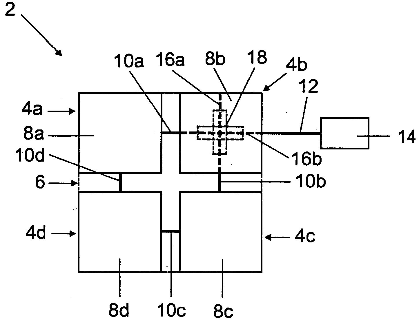
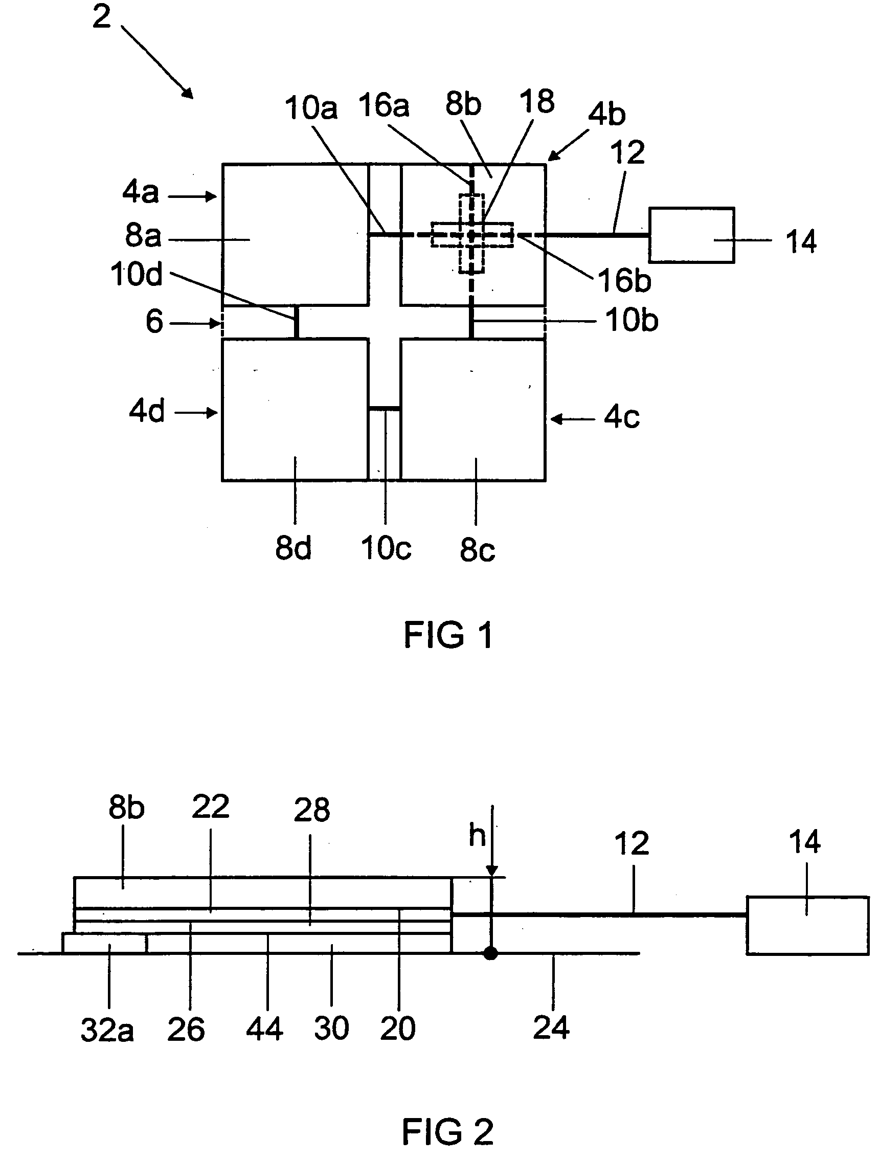
[0003]The invention is based on the object of providing a light module with a backlit surface element which allows substantially uniform illumination of a surface element and has a low physical height. Furthermore, it is the object of the invention to provide a light system for forming a backlit area.
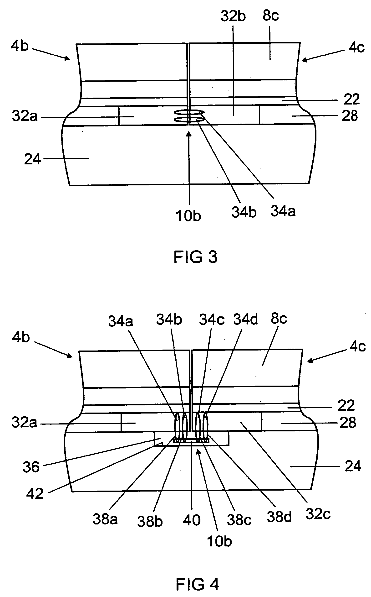
[0005]The light module according to the invention has a surface element, which is backlit by means of a light source. According to the invention, the light source bears flat against the surface element or is connected to it. The flat arrangement of the light source on the surface element means that the latter is backlit over the whole area and in particular uniformly. As a result, a very good backlighting effect can be achieved since the surface element does not have only one LED directed at it as in the above-described prior art. Furthermore, an advantage of the solution according to the invention is the fact that the mount for holding the light source is no longer required, with the result that the light module has a very low physical height.
[0008]In order to avoid damage to the light source, it can be covered at the rear by a protective layer, for example a vapor barrier.
[0009]In order to fix the light module on a fixing surface, it may be advantageous if the protective layer is covered at the rear by a backing layer, for example made from plastic.
[0010]In order to be able to connect adjacent light modules electrically to one another, each light module can have at least one plug. This is preferably fixed in the backing layer and can protrude at the side or at the rear, i.e. in the direction of the fixing surface. If the plugs extend in the direction of the fixing surface it is advantageous if a connecting body can be inserted into a receptacle of the fixing surface, which connecting body can be used to produce the electrical contact between the plugs of the adjacent light modules.
[0011]In order to enable individual driving of the light modules, they can have a switch, which is preferably arranged in the region of intersecting conductor tracks for looping through the current from one light module to the next light module and is protected against damage in the backing layer.

Problems solved by technology

One disadvantage with this solution, however, is the fact that uniform, flat backlighting of the tiles is not achieved by means of the LED.
A further disadvantage is the fact that the LED and the mount have a relatively high physical height.

Method used


Image

  • Light Module and Light System
  • Light Module and Light System
  • Light Module and Light System

Examples


Embodiment Construction

[0003]The invention is based on the object of providing a light module with a backlit surface element which allows substantially uniform illumination of a surface element and has a low physical height. Furthermore, it is the object of the invention to provide a light system for forming a backlit area.

[0004]These objects are achieved by a light module having the features as claimed in patent claim 1 or by a light system having the features as claimed in patent claim 10. Particularly advantageous embodiments of the invention are described in the dependent patent claims.

[0005]The light module according to the invention has a surface element, which is backlit by means of a light source. According to the invention, the light source bears flat against the surface element or is connected to it. The flat arrangement of the light source on the surface element means that the latter is backlit over the whole area and in particular uniformly. As a result, a very good backlighting effect can be ...


PUM


Abstract

The invention relates to a light module comprising a backlit surface element, a light source flatly applied to said surface element or connected thereto and to a light system comprising a plurality of said light modules.

Description

TECHNICAL FIELD[0001]The invention relates to a light module with a backlit surface element in accordance with the preamble of patent claim 1 and to a light system for forming a backlit area.PRIOR ART[0002]Backlighting a surface element has been known for years from, for example, advertisement boards, traffic signals and direction signs. Recently, however, there has been a demand for individual backlighting of individual subsurface elements, which are assembled to form a mosaic area. This has been observed to an increased extent in the sanitation sector, in which targeted backlighting of individual tiles of a tiled area is desired. In order to backlight the respective tiles, US 2005 / 0116667 A1, for example, proposes, in FIG. 46, backlighting the individual tiles by means of a light-emitting diode (LED) which has been inserted into a mount. One disadvantage with this solution, however, is the fact that uniform, flat backlighting of the tiles is not achieved by means of the LED. A fur...

Claims


Application Information

Patent Timeline
IPC IPC(8): F21V17/00F21K99/00
CPCE04F2290/026F21V33/006H05B33/04G02B6/0011F21Y2105/00H05B45/60H05B47/18
Inventor CUSTODIS, UDO
Owner PATENT TREUHAND GESELLSCHAFT FUR ELECTRIC GLUEHLAMPEN MBH
Learn More