Computer Room Environmental Conditioning Unit with Translatable Blowers

a technology of environmental conditioning and blower, which is applied in the direction of piston pumps, heating types, lighting and heating apparatuses, etc., can solve the problems of increasing the cost of changing the location of the blower, and laborious, and achieves the effects of reducing cost and expense, facilitating the installation of the conditioning unit, and easy translation

Active Publication Date: 2009-05-21
VERTIV CORP
View PDF19 Cites 30 Cited by
  • Summary
  • Abstract
  • Description
  • Claims
  • Application Information

AI Technical Summary

Benefits of technology

[0006]A conditioning unit according to the present teachings can advantageously allow the blower to be easily translated from a first operable position in the conditioning unit to a second operable position external to the conditioning unit. The translation of the blower does not require the disconnection of the blower and, accordingly, does not require that the blower be disconnected and reconnected to the control system. Such capability can facilitate the installation of the conditioning unit into a variety of applications and allows the purchaser to customize the blower l

Problems solved by technology

Such tasks can be labor intensive and can increas

Method used


Image

  • Computer Room Environmental Conditioning Unit with Translatable Blowers
  • Computer Room Environmental Conditioning Unit with Translatable Blowers
  • Computer Room Environmental Conditioning Unit with Translatable Blowers

Examples


first embodiment

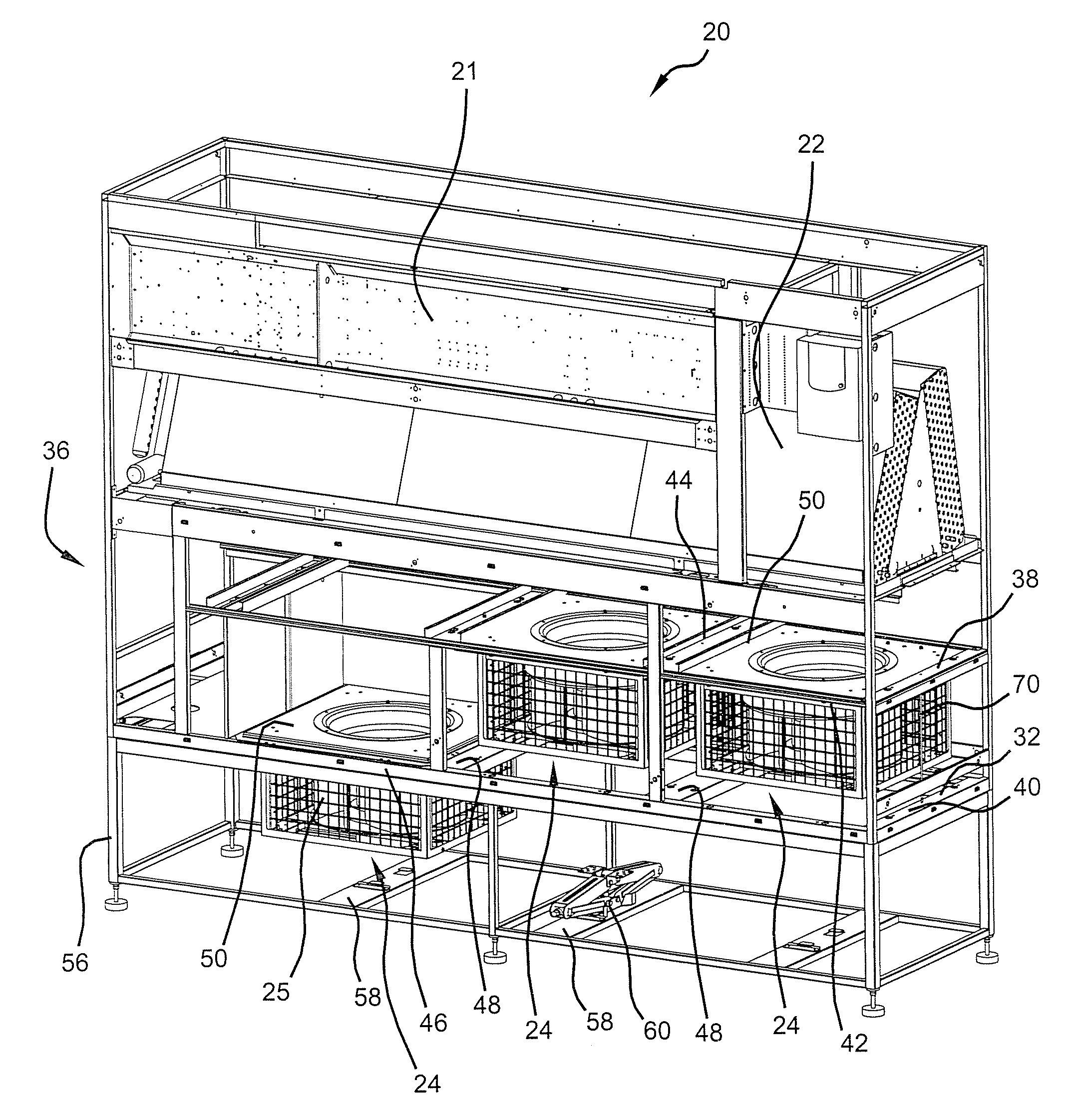
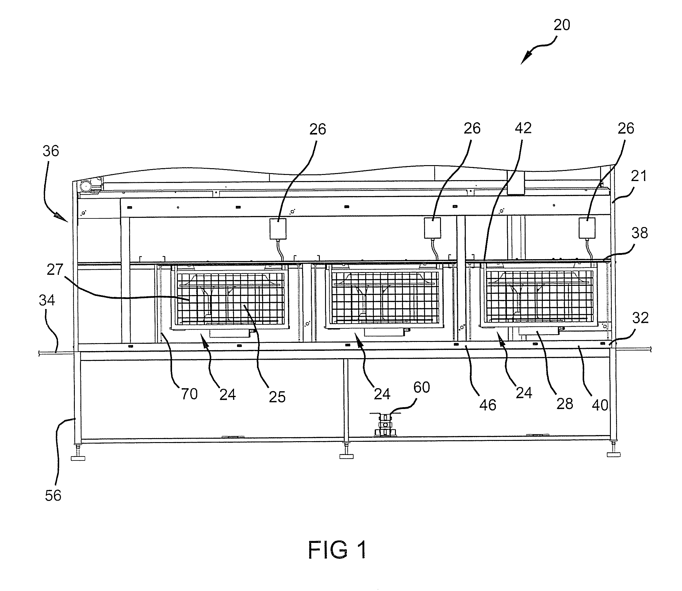
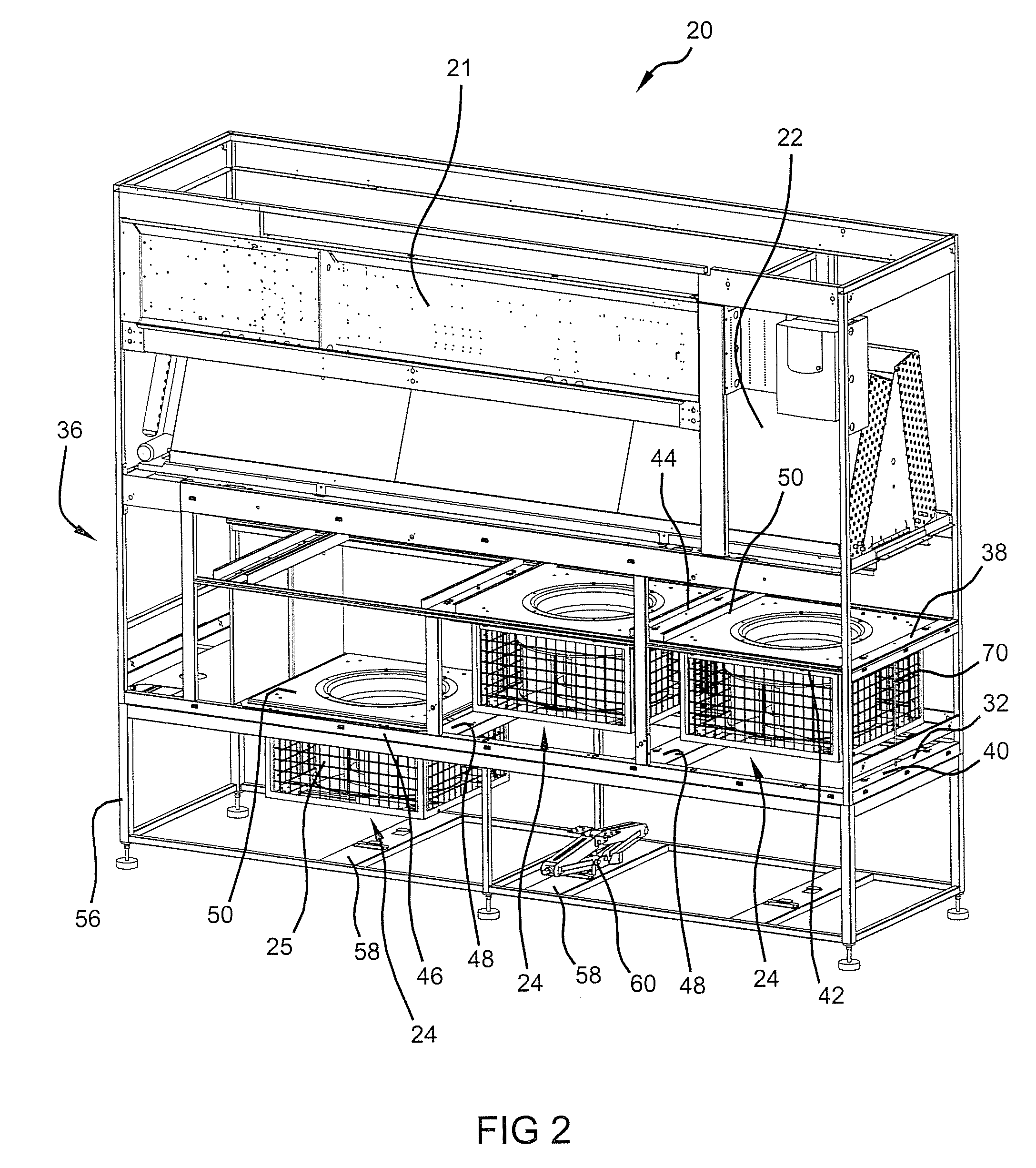
[0032]Referring to FIGS. 1-6, a computer room environmental conditioning unit 20 with translatable blowers according to the present teachings is shown. Conditioning unit 20 is illustrated in a simplified form without all of the details shown. Conditioning unit 20 includes a plurality of panels 21 that surround and enclose conditioning unit 20 and form a cabinet. Conditioning unit 20 includes a variety of components that are operable to condition an air flow flowing therethrough. Conditioning unit 20 includes a heat exchanger 22 which is operable to transfer heat between a fluid flowing through heat exchanger 22 and an air flow flowing across heat exchanger 22. Heat exchanger 22 can take a variety of forms. As a non-limiting example, one type of heat exchanger includes a fin on tube heat exchanger wherein the heat transfer fluid flows through the tubes and the air flow flows across the fins. Conditioning unit 20 includes a plurality of blowers 24 that are operable to direct the air f...

second embodiment

[0043]Referring now to FIGS. 7-9, a computer room environmental conditioning unit 120 having blowers 124 that can be moved between first and second operative positions according to the present teachings is shown. Conditioning unit 120 is similar to conditioning unit 20 discussed above. As such, not all of the details of conditioning unit 120 will be described.

[0044]In conditioning unit 120, blowers 124 are moved between the first and second operative positions with a jig assembly 172. Jig assembly 172 includes an upper support member 174 and a lower support member 176 that can be moved relative to one another with a threaded rod 178. Each support member 174, 176 includes a centrally located opening 180 that aligns with one another and is configured to receive threaded rod 178. Threaded rod 178 can be inserted through and engaged with central openings 180 of support members 174, 176 with the head 179 of threaded rod 178 and a washer 173 adjacent the lower surface of lower support mem...

third embodiment

[0050]Referring now to FIGS. 10-14, a conditioning unit 220 that allows a blower 224 to be moved between first and second positions according to the present teachings is shown. Conditioning unit 220 is similar to conditioning unit 20 discussed above. Thus, all the details of conditioning unit 220 will not be described. In conditioning unit 220, however, blowers 224 are intended to be used only in the second lowered position. In conditioning unit 220, blowers 224 pivot between the first shipped position and the second lowered and operable position. In FIGS. 10-12, the rightmost blower 224 is shown in the first shipped position, while the middle and left blowers 224 are shown in the second operative position wherein blowers 224 are disposed in the space beneath raised floor 234.

[0051]Blowers 224 are pivotally secured to the rear longitudinal support member 246 of lower level 240 of structural assembly 236. One end of flange 250 of each blower 224 has a bracket 290 that extends therefr...


PUM


Abstract

A conditioning unit can allow the blower to be easily translated from a first operable position in the conditioning unit to a second operable position external to the conditioning unit. The translation of the blower does not require the disconnection of the blower and, accordingly, does not require that the blower be disconnected and reconnected to the control system. Such capability can facilitate the installation of the conditioning unit into a variety of applications and allows the purchaser to customize the blower location based on the desired performance. The ability to customize the installation of the conditioning unit without requiring disconnection and reconnection of the blower can reduce the cost and expense associated with the installation into differing applications.

Description

CROSS-REFERENCE TO RELATED APPLICATIONS[0001]This application claims the benefit of U.S. Provisional Application No. 60 / 989,741, filed on Nov. 21, 2007. The disclosure of the above application is incorporated herein by reference.FIELD[0002]The present invention relates to computer room environmental conditioning units and, more particularly, to conditioning units wherein the blower is translatable between different positions.BACKGROUND AND SUMMARY[0003]The statements in this section merely provide background and summary information related to the present teachings and may not constitute prior art.[0004]Computer rooms utilize environmental conditioning unit(s) to condition the environment within which the computer equipment is located. The conditioning unit includes a heat exchanger through which air within a computer room is drawn to condition the air. A blower is utilized to draw air through the conditioning unit and across the heat exchanger. The conditioning unit is typically inc...

Claims


Application Information

Patent Timeline
IPC IPC(8): F04D15/00
CPCF04D25/10F04D29/582F24F2221/40F24F1/0033F24F13/08F04D29/601H05K7/20718H05K7/20745
Inventor SCHUTTE, DANIEL J.HELMINK, GARY A.DOUGLAS, DAVID W.DOLCICH, BENEDICT J.ZHONG, ANFUXU, GANGMARTON, LEWISANJOS, LUIS A.BUCKINGHAM, PETER M.
Owner VERTIV CORP
Why Eureka
Try Eureka