Aircraft cart transport and stowage system

a technology for aircraft and stowage areas, which is applied in the direction of transportation and packaging, aircraft crew accommodation, galleys, etc., can solve the problems of increasing the difficulty of stowage cart manipulation, the difficulty of moving and manipulating service carts in these areas, and the weight of service carts such as the one of the passenger cabins is difficult to manipulate, so as to prevent operator injuries, easy to spatially integrate within the aircraft, and eliminate the disadvantages

Active Publication Date: 2009-02-24
THE BOEING CO
View PDF45 Cites 13 Cited by
  • Summary
  • Abstract
  • Description
  • Claims
  • Application Information

AI Technical Summary

Benefits of technology

[0009]The embodiments of the present invention provide several advantages. One such advantage is the provision of an automated service cart transport system that is ergonomically pleasing. This provision minimizes manual service cart manipulation and thus allows for easy movement, translation, stowage, and removal therefrom of service carts within an aircraft.
[0015]Furthermore, the above stated advantages provide increased utility and space efficiency of crew cabin, galley, passenger, and stowage areas of an aircraft. The stated advantages increase the available space on a main deck, preserve the stowage of an overhead galley or stowage area, and preserve the payload capacity of a lower lobe or cargo bay of an aircraft.

Problems solved by technology

Spaces within the overhead stowage and lower lobe areas can be confined and thus movement and manipulation of service carts within these areas can be difficult.
In tight spaces, service carts of such weight are difficult to manipulate.
This binding can further increase the difficulty in manipulation of the service carts.

Method used


Image

  • Aircraft cart transport and stowage system
  • Aircraft cart transport and stowage system
  • Aircraft cart transport and stowage system

Examples


Embodiment Construction

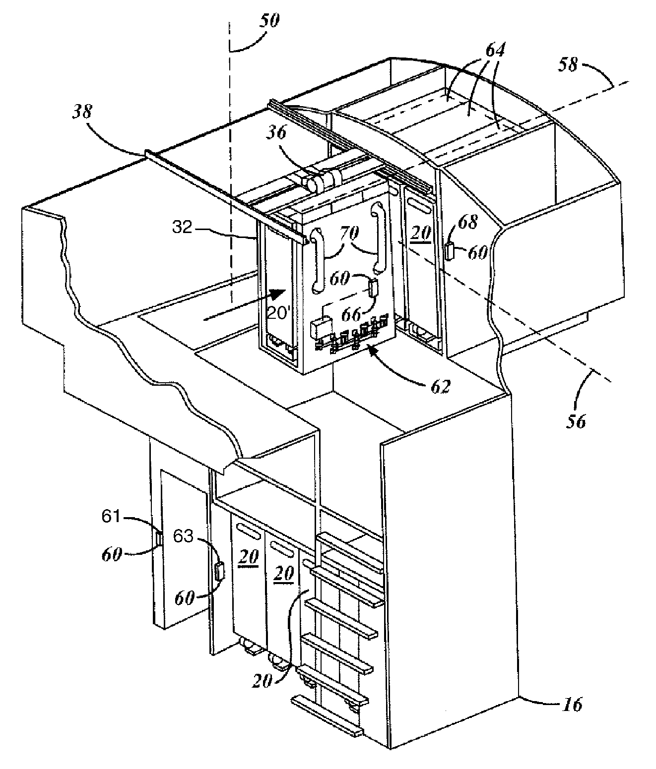
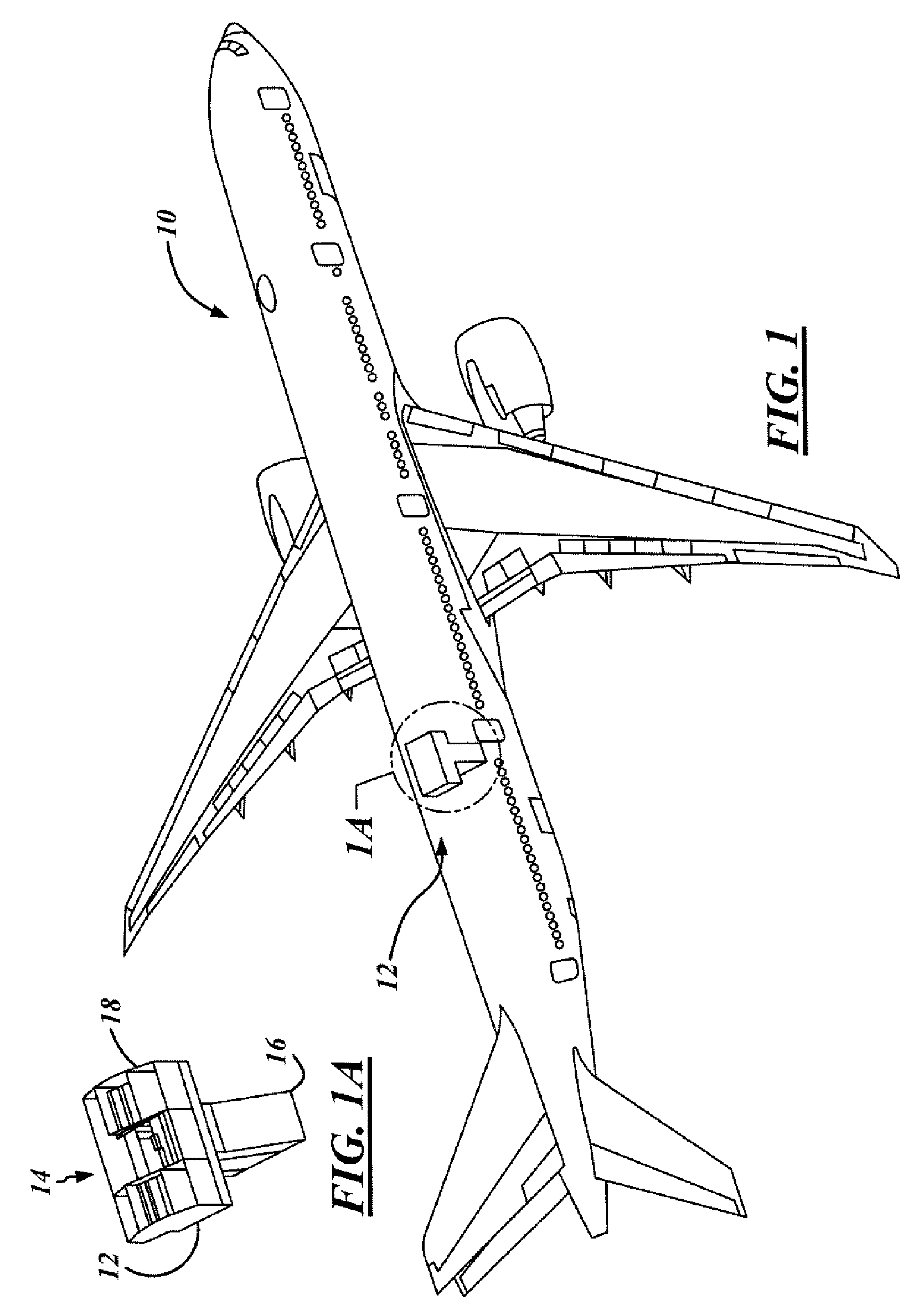
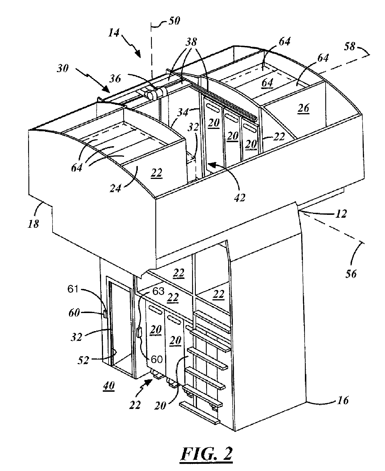
[0030]In the following Figures the same reference numerals will be used to refer to the same components. While the present invention is described primarily with respect to an integrated transport and stowage system for the transporting of service carts within an aircraft, the present invention may be adapted and applied in various applications. The present invention may be applied in aeronautical applications, nautical applications, railway applications, automotive vehicle applications, and commercial and residential applications. The present invention may also be applied to various areas of an aircraft including galleys, overhead areas, main deck areas, lower lobe areas, passenger cabin areas, crewmember and non-crewmember areas, as well as other areas of an aircraft. Also, a variety of other embodiments are contemplated having different combinations of the below described features of the present invention, having features other than those described herein, or even lacking one or m...


PUM


Abstract

An object transport and stowage system for an aircraft (10) includes a transport unit (32) for the transport of an object (20) within the aircraft (10). A first transfer drive system (62) is attached to the transport unit (32) and includes object engagement devices (92) that are engagable with the object (20). A motor (120) is mechanically coupled to and rotates one or more of the object engagement devices (92). A controller (66) is electrically coupled to the motor (120) and translates the object (20) relative to the transport unit (32). Another object transport and stowage system for an aircraft (10) includes a housing (150) for the stowage of an object (20) on the aircraft (10). A transfer drive system (64′) is attached to the housing (150) and includes object engagement devices (168, 176), which are engagable with the object (20). A motor (162) is mechanically coupled to and rotates one or more of the object engagement devices (168, 176). A controller (68) is electrically coupled to the motor (162) and translates the object (20) relative to the housing (150).

Description

RELATED PATENTS[0001]The present application is related to U.S. Pat. No. 6,971,608 issued on Dec. 6, 2005 and U.S. Pat. No. 7,159,821 issued on Jan. 9, 2007, the latter being a continuation-in-part of U.S. application Ser. No. 10 / 708,955 filed on Apr. 2, 2004, now U.S. Pat. No. 6,971,608.TECHNICAL FIELD[0002]The present invention is related generally to service carts, galleys, passenger cabins, and stowage areas of an aircraft. More particularly, the present invention is related to the transporting and stowage of service carts within an aircraft and to the efficient utilization of the stated areas.BACKGROUND OF THE INVENTION[0003]Modern aircraft typically include passenger compartments, galley service areas, overhead areas, and various stowage areas, which may be located on one or more decks. The galley areas often include and have associated therewith multiple service carts. The service carts contain various service related items, such as beverages and food items. The service carts...

Claims


Application Information

Patent Timeline
Patent Type & Authority Patents(United States)
IPC IPC(8): B64D11/00B66C17/00
CPCB64D11/0007B64D11/04
Inventor HARRINGTON, ANTHONY A.BAZZELL, GARY L.
Owner THE BOEING CO
Why Eureka
Try Eureka