Apparatus and method for detecting an image

Active Publication Date: 2009-08-06
FRAUNHOFER GESELLSCHAFT ZUR FOERDERUNG DER ANGEWANDTEN FORSCHUNG EV
View PDF12 Cites 13 Cited by
  • Summary
  • Abstract
  • Description
  • Claims
  • Application Information

AI Technical Summary

Benefits of technology

[0026]These individual images may then be composed using a computer, it being advantageous to ensure that the subregions will overlap so as to prevent any image losses, that is non-picked-up locations of the scintillator screen, from occurring even with relatively small misalignments.
[0027]The present invention therefore enables subdividing the scintillator screen into basically any number of optical cameras in

Problems solved by technology

The non-absorbed X-ray quanta may be absorbed by the underlying semiconductor layer, thereby damaging same.
Given an appropriate dose, this radiation damage will eventually cause the detector to fail.
What is disadvantageous about the concept depicted in FIGS. 5 and 6 is that the structural height perpendicular to the scintillator screen is reduced since the sensors are arranged laterally.
But

Method used


Image

  • Apparatus and method for detecting an image
  • Apparatus and method for detecting an image
  • Apparatus and method for detecting an image

Examples


Embodiment Construction

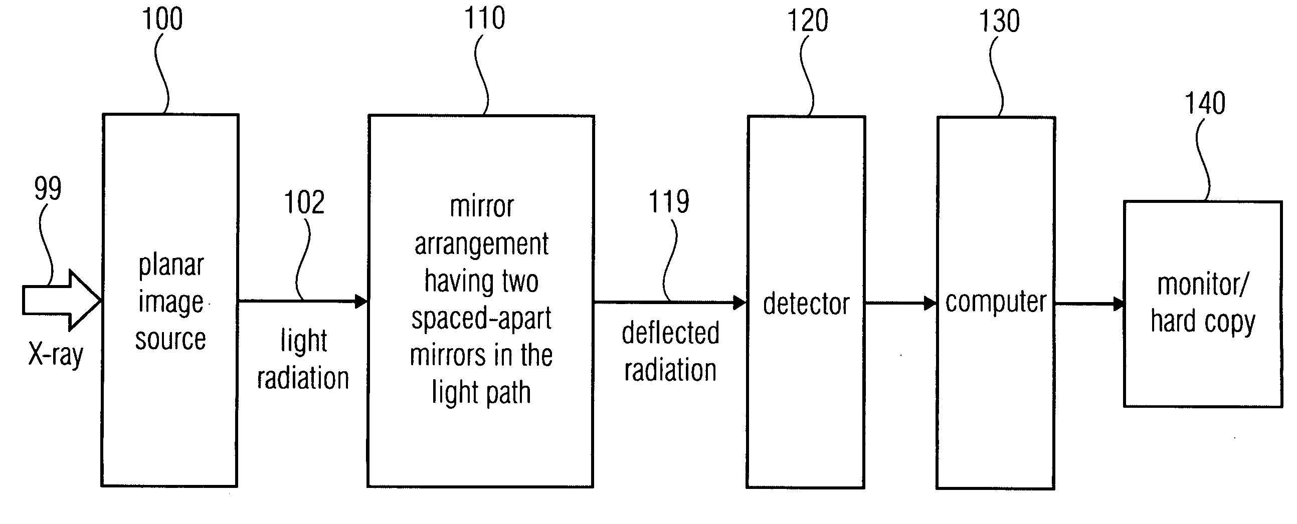
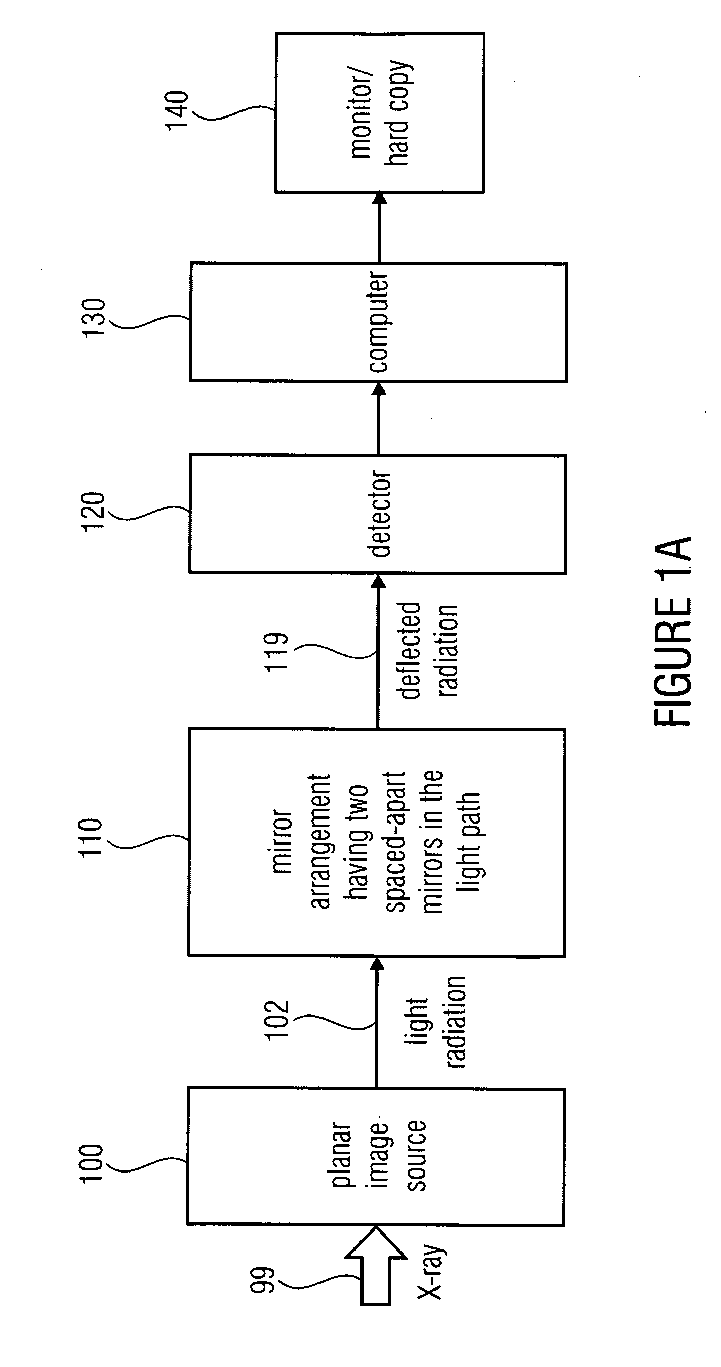
[0038]FIG. 1a shows a schematic representation of the apparatus for detecting an image. The apparatus for detecting an image comprises a planar image source 100 and a mirror arrangement 110 for deflecting radiation which may be generated by the image source 100. The light radiation generated by the planar image source 100 is schematically depicted at 102. Thus, the mirror arrangement 110 receives the light radiation 102 at the input side, and outputs deflected light radiation 119 which will impinge on a detector 120. The detector is configured to receive the light, or the radiation, 119 deflected by the mirror arrangement 110. At the output side, the detector 120 may be connected to a computer 130, which outputs the image generated by the planar image source 100 via a monitor or a printer in the form of a printed copy (hard copy) or as a file (soft copy). Therefore, the device 140 may be a memory, a monitor, a printer or, e.g., a communication interface so as to transmit the image t...


PUM

PropertyMeasurementUnit
Fractionaaaaaaaaaa
Angleaaaaaaaaaa
Angleaaaaaaaaaa

Abstract

In order to detect an image generated by an image source, a mirror arrangement is arranged between the image source and a detector. The mirror arrangement includes two spaced-apart deflection mirrors, which are parallel to each other or form an acute angle of less than 90° between them. In particular when the image source is a scintillator layer, shielding of X-rays from the detector with simultaneous compact dimensioning of the apparatus is achieved in this manner.

Description

CROSS-REFERENCE TO RELATED APPLICATIONS[0001]This application claims priority from German Patent Application No. 102008007595.7-51, which was filed on Feb. 6, 2008, and from International Patent Application No. PCT / EP2009 / 000669, which was filed on Feb. 2, 2009, which are both incorporated herein in their entirety by reference.[0002]The present invention relates to image detection and, in particular, to image detection of scintillator screens.BACKGROUND OF THE INVENTION[0003]Optical pickup of a planar image source, for example a screen, which may be implemented as a scintillator screen, may be performed using one or more cameras. Such a pickup of a screen is achieved, for example, by an X-ray camera which may be employed in digital radioscopy, for example for product quality control.[0004]In medical radioscopy, so-called flat-panel detectors are currently used. In such flat-panel detectors, X-radiation is typically converted to visible light via a scintillator screen, and said visib...

Claims


Application Information

Patent Timeline
IPC IPC(8): G21K1/00
CPCG01T1/20Y10T29/49826G01T1/2002
Inventor SCHMITT, PETERKOSTKA, GUENTHERBEHRENDT, ROLFKUBE, MATTHIASGROEGER, WOLFGANG
Owner FRAUNHOFER GESELLSCHAFT ZUR FOERDERUNG DER ANGEWANDTEN FORSCHUNG EV
Why Eureka
Try Eureka