Fuel Cell Stack Casing

a fuel cell and stack casing technology, applied in the field of fuel cell stack casing, can solve the problems of reducing the rigidity of the casing, reducing the electrical shield, etc., and achieve the effect of limiting and/or preventing the leakage of electromagnetic waves, and preventing the casing from entering the casing without losing the ventilating ability

Inactive Publication Date: 2009-05-21
TOYOTA JIDOSHA KK
View PDF13 Cites 37 Cited by
  • Summary
  • Abstract
  • Description
  • Claims
  • Application Information

AI Technical Summary

Benefits of technology

[0018]According to the fuel cell stack casing according to item (6) above, since the fuel cell stack casing may include a plurality of members (e.g., an upper casing and a lower casing of an embodiment described hereinafter), and the plurality of the members may be coupled to each other such that conductive materials included in the plurality of members may be caused to be conductive to each other, electromagnetic waves may be prevented from leaking at a coupling portion of the plurality of the casings.
[0020]According to the fuel cell stack casing according to item (8) above, since the fuel cell stack casing may have a plurality of apertures for allowing air to pass therethrough formed in a wall of the fuel cell stack casing and spaced from each other, even if a very small amount of fuel gas leaks from the fuel cell, an interior of the fuel cell stack casing can be ventilated. Further, since the plurality of apertures are spaced from each other, electromagnetic waves may be prevented from passing through the apertures so that electromagnetic shield may be maintained, unlike a case where a single, large aperture is provided and electromagnetic waves pass through the large aperture.
[0022]According to the fuel cell stack casing according to item (10) above, since each of the apertures may have a size smaller than a size at which electromagnetic shield is maintained (e.g., smaller than an aperture of a about 40 mm in diameter), leakage of electromagnetic wave may be limited and / or prevented when the apertures are used as ventilation apertures.
[0023]According to the fuel cell stack casing according to item (11) above, since the plurality of apertures may be covered by a cover made from a material which allows air to pass therethrough and does not allow water to pass therethrough, water can be prevented from entering the casing without losing a ventilating ability of the casing. When providing the cover, by providing a conductive material in the material of the cover and by conducting the conductive material of the cover to the casing, the electromagnetic shield may be maintained even if a size of each of the apertures is made large.

Problems solved by technology

However, there are the following problems with conventional fuel cell stack casings: (i) because metal is used, the weight of the casings may be large; (ii) in a case where a ventilation aperture is provided, the casing size is determined so that a necessary ventilation may be obtained, thus a electromagnetic shield may be decreased, and as a result, an electromagnetic wave may pass through the aperture; and (iii) certain materials may cause the rigidity of the casing to be decreased.

Method used


Image

  • Fuel Cell Stack Casing
  • Fuel Cell Stack Casing
  • Fuel Cell Stack Casing

Examples


embodiment 1

>

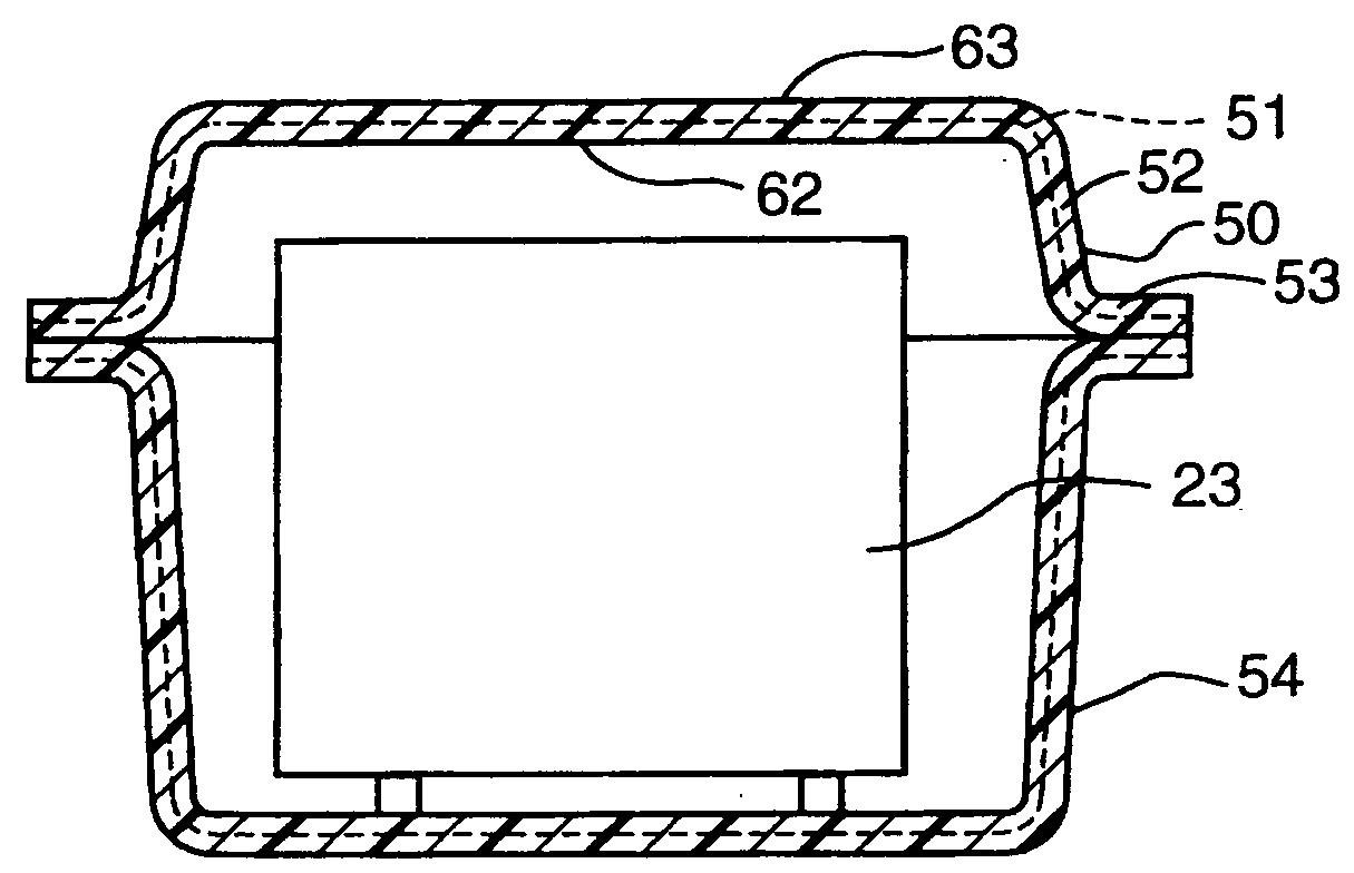
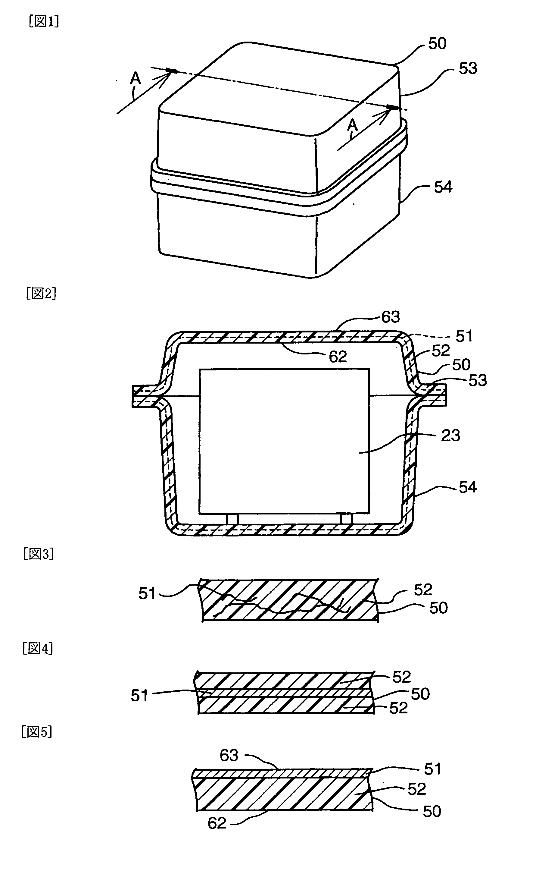
[0074]In embodiment 1, as illustrated in FIG. 3, resinification of the fuel cell stack casing 50 is performed by causing the resin (for example, polyethylene) to contain conductive material 51 (for example, an aluminum filler, a graphite filler of a schuppen structure, etc.) The conductive materials 51 exist at random in the resin 52 and contact with each other to be electrically connected to each other. In a case where a part of conductive materials 51 is exposed to the inside surface 62 of the casing 50, an electrical insulator is desired to be provided between the fuel cell stack casing 50 and the fuel cell stack 23.

[0075]In other words, plural conductive elements having conductivity exist in parts of the fuel cell stack casing 50 (for example, the upper casing 53 and the lower casing 54) such that the plural conductive elements contact with each other and in a substantially planar state. These conductive elements are, for example, fibers, sphericals, or particles and are suffic...

embodiment 2

>

[0078]In embodiment 2, as illustrated in FIG. 4, resinification of the fuel cell stack casing 50 is performed by sandwiching a conductive layer 51 (for example, an aluminum thin plate, a graphite plate of a schuppen structure, etc., the same hereinafter) between two layers made from a non-conductive resin 52 (for example, polyethylene). The conductive layer 51 is not exposed to inside and outside surfaces of the casing 50.

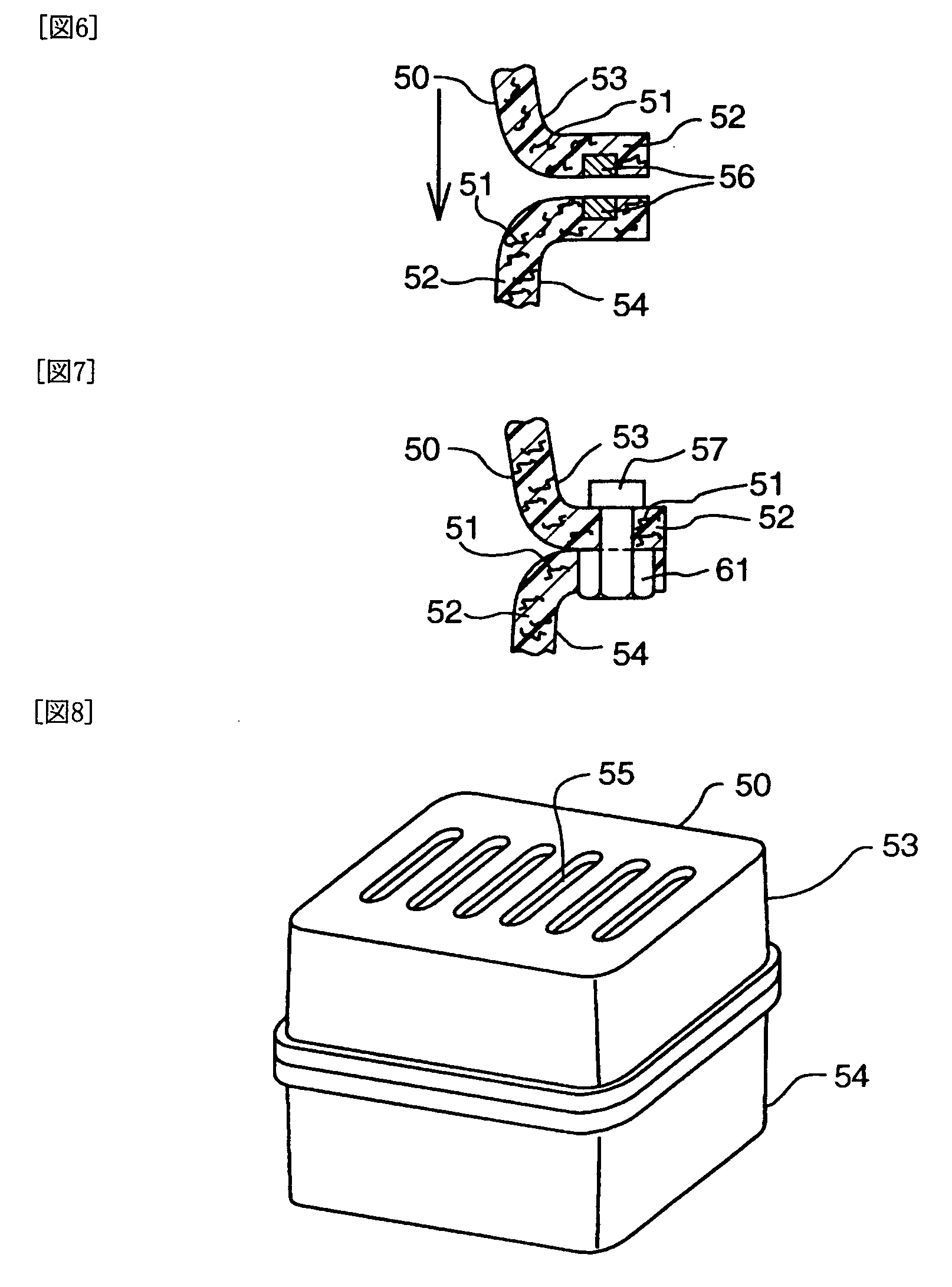
[0079]With effects and technical advantages of embodiment 2 of the present invention, since during resinification of the fuel cell stack casing 50 the conductive layer 51 is performed between two layers made from a non-conductive resin 52, an electromagnetic shield can be formed over the entire plane of the wall of the casing. Since the conductive layer 51 is not exposed to the inside surface of the casing 50, there is no need to provide an electric insulator between the fuel cell stack 23 and the casing 50. Further, an electromagnetic shield of the coupling porti...

embodiment 3

>

[0081]In embodiment 3, as illustrated in FIG. 5, resinification of the fuel cell stack casing 50 is performed by layering a layer made from a non-conductive resin 52 (for example, polyethylene) and a layer of conductive material 51 (for example, an aluminum thin plate, a graphite plate of a schuppen structure, etc., the same hereinafter) provided on an outside surface 63 side of the casing (or on an inside surface 62 side of the casing, and in a case where the conductive material layer is provided on the inside surface side of the casing, an electric insulator is required to be provided on the inner side of the conducting material layer). The conductive surface 51 provided on the outside surface of the casing may be made by adhering an aluminum leaf on the casing. The conductive layer 51 is not exposed to the inside surface of the casing 50.

[0082]With effects and technical advantages of embodiment 3 of the present invention, since during resinification of the fuel cell stack casing...


PUM

PropertyMeasurementUnit
diameteraaaaaaaaaa
sizeaaaaaaaaaa
conductiveaaaaaaaaaa

Abstract

A fuel cell stack casing for housing a fuel cell stack. The fuel cell stack casing may include a resin and an electromagnetic wave damping material, for example, a conductive material. In addition, the fuel cell stack may be electromagnetically shielded by the electromagnetic wave damping material. The fuel cell stack casing may include a plurality of members coupled to each other such that conductive materials contained in the members are electrically connected to each other. An inside surface of the casing may be an insulating surface. A plurality of apertures for ventilation may be formed in a wall of the casing such that the apertures are spaced from each other. The apertures may be covered with a cover.

Description

CROSS-REFERENCE TO RELATED APPLICATIONS[0001]This is a 371 national phase application of PCT / JP2006 / 320907, filed 20 Oct. 2006, claiming priority to Japanese Patent Application No. 2005-305583, filed 20 Oct. 2005, the entire contents of which are hereby incorporated by reference.TECHNICAL FIELD[0002]The present invention relates to a fuel cell stack casing for housing a fuel cell stack.BACKGROUND[0003]A fuel cell includes separators and an MEA disposed between the separators. A plurality of fuel cells layers form a fuel cell stack. The fuel cell stack is housed in the fuel cell stack casing.[0004]Conventional fuel cell stacks may be made of materials such as aluminum or iron, as disclosed in, for example, Japanese Patent Publication 2002-362164, the entire contents of which are hereby incorporated by reference. However, there are the following problems with conventional fuel cell stack casings: (i) because metal is used, the weight of the casings may be large; (ii) in a case where a...

Claims


Application Information

Patent Timeline
Patent Type & Authority Applications(United States)
IPC IPC(8): H01M8/04H01M2/02
CPCH01M8/2405H01M8/2475Y02E60/50H01M2250/20Y02T90/32H01M2008/1095H01M8/0267H05K9/0047H01M8/2457H01M8/2483Y02T90/40
Inventor TANAKA, HIDEYUKI
Owner TOYOTA JIDOSHA KK
Why Eureka
Try Eureka