
Two-piece dental abutment system

a technology of dental implants and abutments, applied in the field of dental implants, can solve problems such as damage to implants

Active Publication Date: 2009-05-21
BIOMET 3I LLC
View PDF6 Cites 68 Cited by
  • Summary
  • Abstract
  • Description
  • Claims
  • Application Information

AI Technical Summary

Problems solved by technology

Since a ceramic support post is of greater hardness than a titanium implant, the ceramic may cause damage to the implant.

Method used


Image

  • Two-piece dental abutment system
  • Two-piece dental abutment system
  • Two-piece dental abutment system

Examples


Embodiment Construction

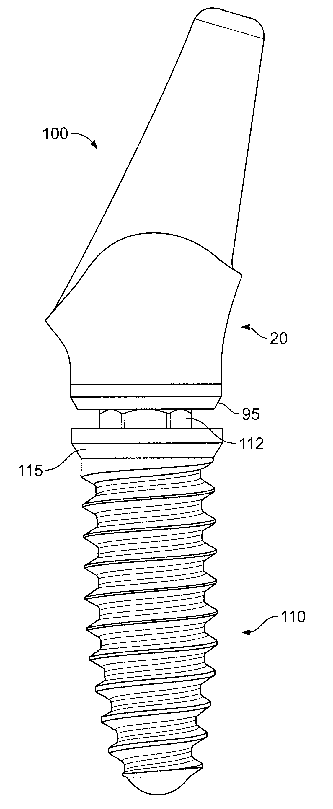
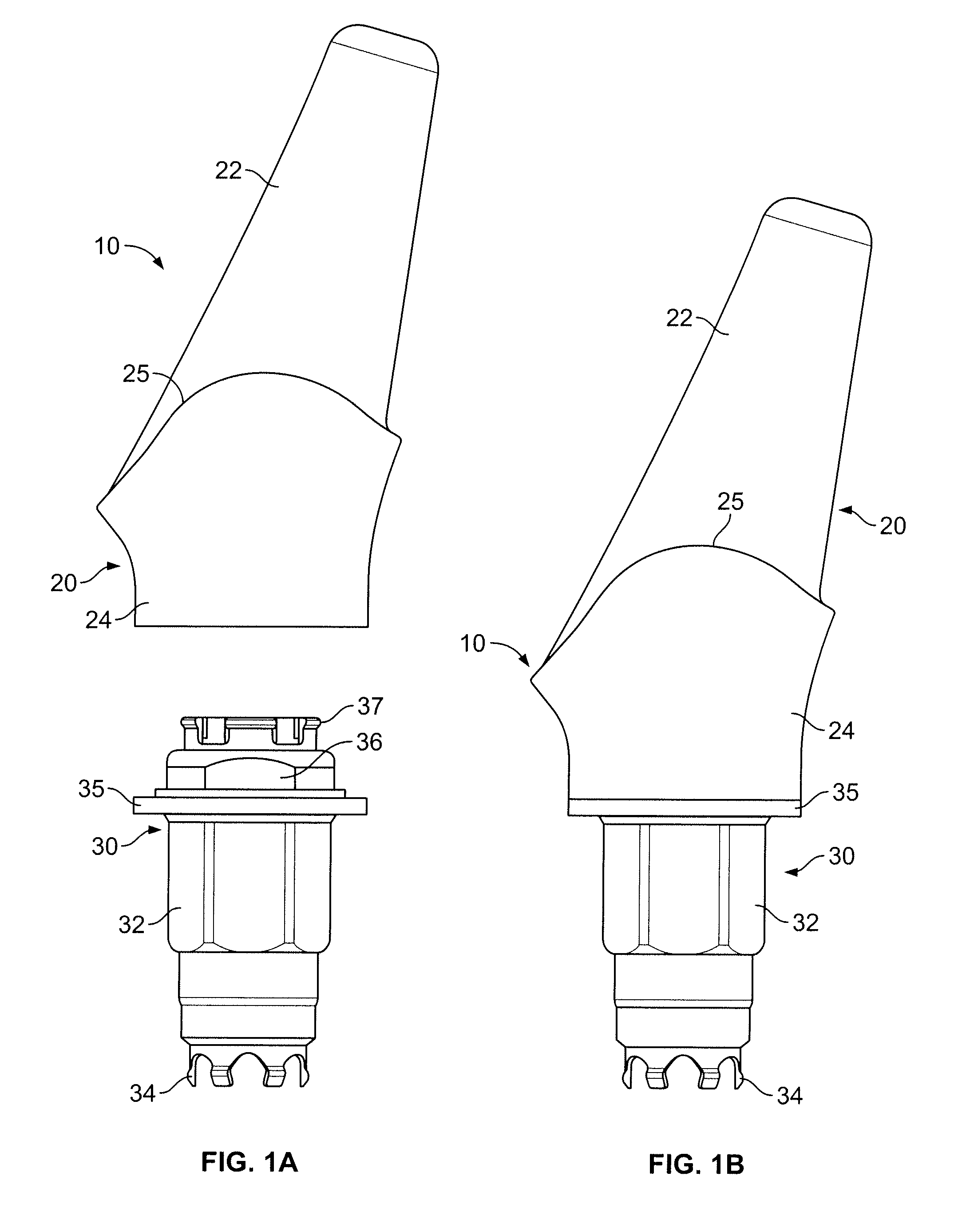
[0021]FIGS. 1A and 1B illustrate a two-piece abutment 10, which includes a prosthetic portion 20 and an insert 30. The prosthetic portion 20 includes a support region 22 and a subgingival region 24. The support region 22 and the subgingival region 24 are separated by a shoulder 25. In operation, tooth-like material, such as porcelain, is formed into the size and shape of a natural tooth and is mounted on the support region 22, interfacing at the shoulder 25. The shoulder 25 is typically just below the gingival tissue.

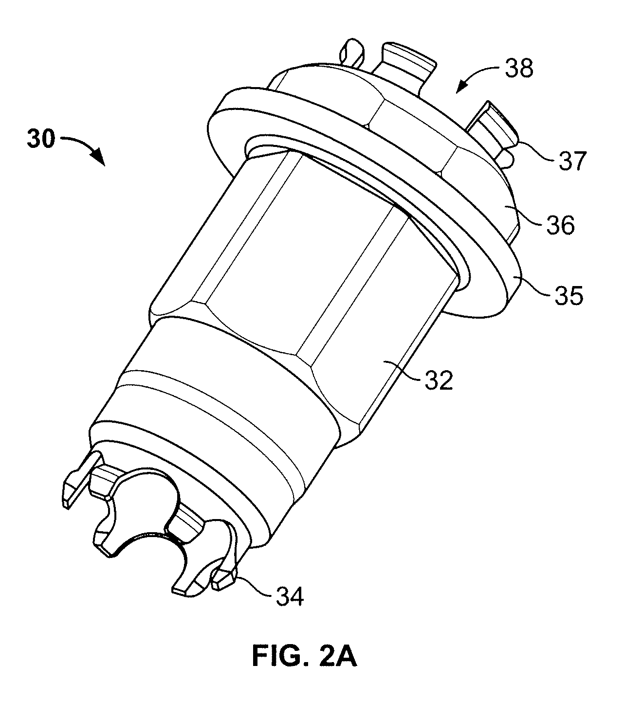
[0022]The insert 30 includes an anti-rotational feature 32 (e.g., a hexagonally shaped region) and an axial engagement section 34. The axial engagement section 34 comprises a plurality of prongs that snap outwardly into a corresponding feature within an internal bore of an implant to hold the two-piece abutment 10 on the implant.

[0023]The insert 30 further includes a table 35 that interfaces with the prosthetic portion 20, as shown best in FIG. 1B. Above the table 35, t...


PUM


Abstract

The present inventions is an abutment for use with a dental implant. The abutment comprises a prosthetic portion adapted to support a prosthesis thereon and an insert. The prosthetic portion has a subgingival end and a supragingival region for protruding beyond gingiva adjacent to the dental implant. The prosthetic portion has a passageway extending therethrough. The passageway includes an enlarged retention groove and non-round section. The insert extends into the passageway and engages the subgingival end of the prosthetic portion. The insert includes flexible retention fingers that, upon insertion into the passageway, initially contract before reaching the enlarged retention groove and then expand outwardly into the enlarged retention groove to hold the insert onto the prosthetic portion. The insert also has a non-round section for mating with the non-round section of the passageway.

Description

CROSS REFERENCE TO RELATED APPLICATION[0001]This application claims the benefit of the U.S. Provisional Application No. 61 / 003,200, filed on Nov. 15, 2007, which is hereby incorporated by reference in its entirety.FIELD OF INVENTION[0002]The present invention relates generally to dental implant systems. More particularly, the present invention relates to a two-piece abutment system.BACKGROUND OF THE INVENTION[0003]The dental restoration of a partially or wholly edentulous patient with artificial dentition is typically done in two stages. In the first stage, an incision is made through the gingiva to expose the underlying bone. After a series of drill bits creates an osteotomy in the bone, a dental implant is placed in the jawbone for integration. The dental implant generally includes a threaded bore to receive a retaining screw holding mating components therein. During the first stage, the gum tissue overlying the implant is sutured and heals as the osseointegration process continue...

Claims


Application Information

Patent Timeline
Patent Type & Authority Applications(United States)
IPC IPC(8): A61C8/00
CPCA61C8/005A61C8/0062A61C8/006A61C8/0071A61C8/0068
Inventor TOWSE, ROSS W.BELLANCA, JOHN J.POWELL, THEODORE M.GOODMAN, RALPH E.
Owner BIOMET 3I LLC
Learn More