Portable telephone with broadcast receiver

a receiver and telephone technology, applied in the direction of collapsible antennas, electromagnetic wave modulation, television systems, etc., can solve the problems of low antenna performance, degraded antenna efficiency, and low reception sensitivity, and achieve high cell phone communication performance and high reception sensitivity

Inactive Publication Date: 2009-05-21
PANASONIC CORP
View PDF7 Cites 43 Cited by
  • Summary
  • Abstract
  • Description
  • Claims
  • Application Information

AI Technical Summary

Benefits of technology

[0037]As described above, according to the invention, it is possible to obtain a high receiving sensitivity at all times in a variety of use states including a sta

Problems solved by technology

In case the related antenna described in JP-A-10-084209 is housed in a clamshell cell phone having a structure where the upper and lower housings can be folded about a hinge as an axis, an antenna element housed in either housing is in proximity to a conductor having a ground potential such as a circuit board or a shield case in the other housing when the cell phone is folded, thus resulting in lower antenna performance and degraded receiving sensitivity.
A compact-size broadcast receiving antenn

Method used


Image

  • Portable telephone with broadcast receiver
  • Portable telephone with broadcast receiver
  • Portable telephone with broadcast receiver

Examples


first embodiment

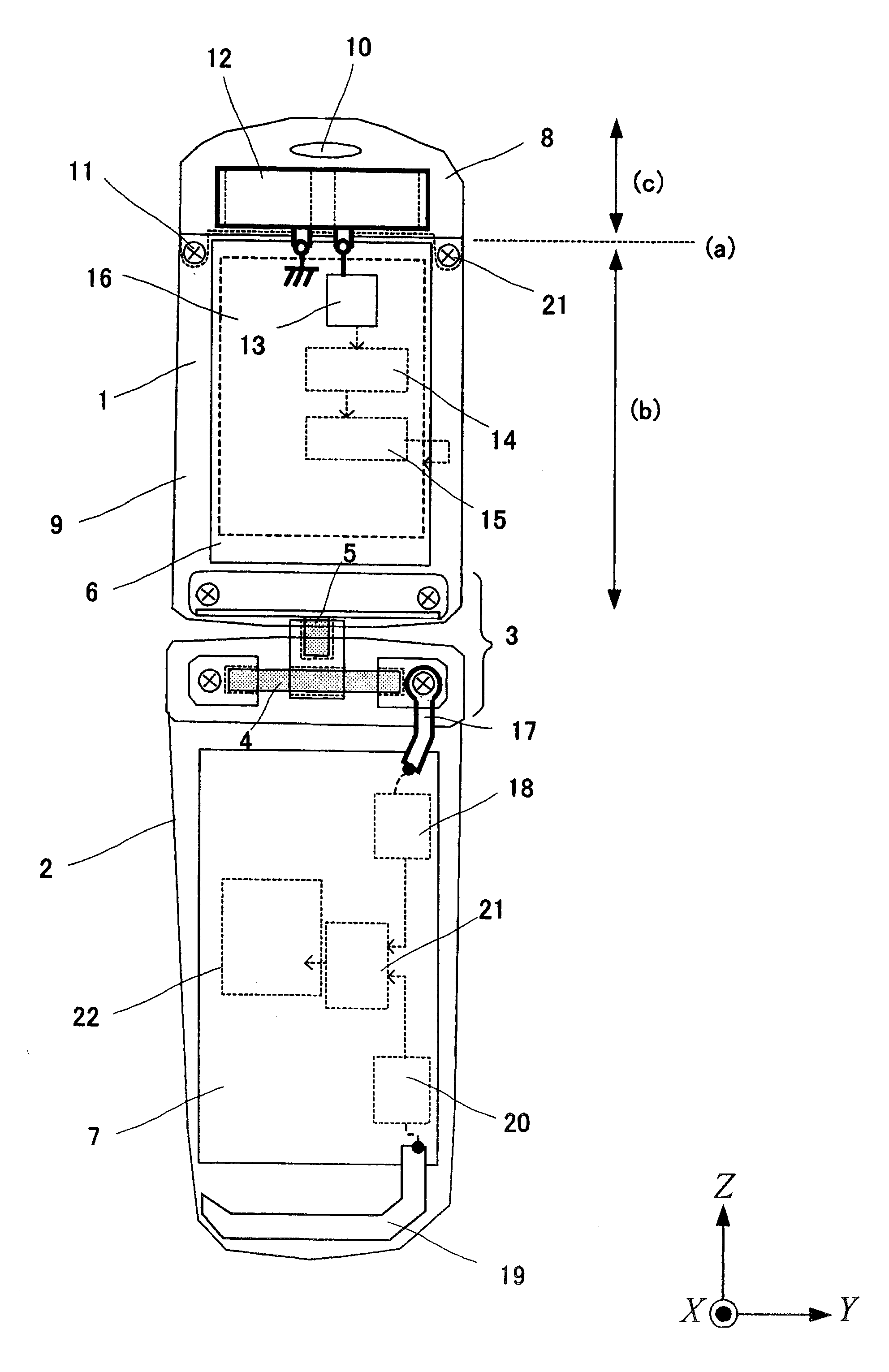
[0057]FIG. 1 is a front view of the basic configuration of a cell phone equipped with a broadcast receiver according to the first embodiment of the invention. FIGS. 2 through 6 illustrate the open and closed states of the housings of the cell phone equipped with a broadcast receiver according to the first embodiment.

[0058]As shown in FIG. 1, the cell phone equipped with a broadcast receiver according to this embodiment has a folding structure where an upper housing 1 and a lower housing 2 are rotatably supported by a hinged part 3. FIG. 1 shows the upper housing 1 and the lower housing 2 in the open state.

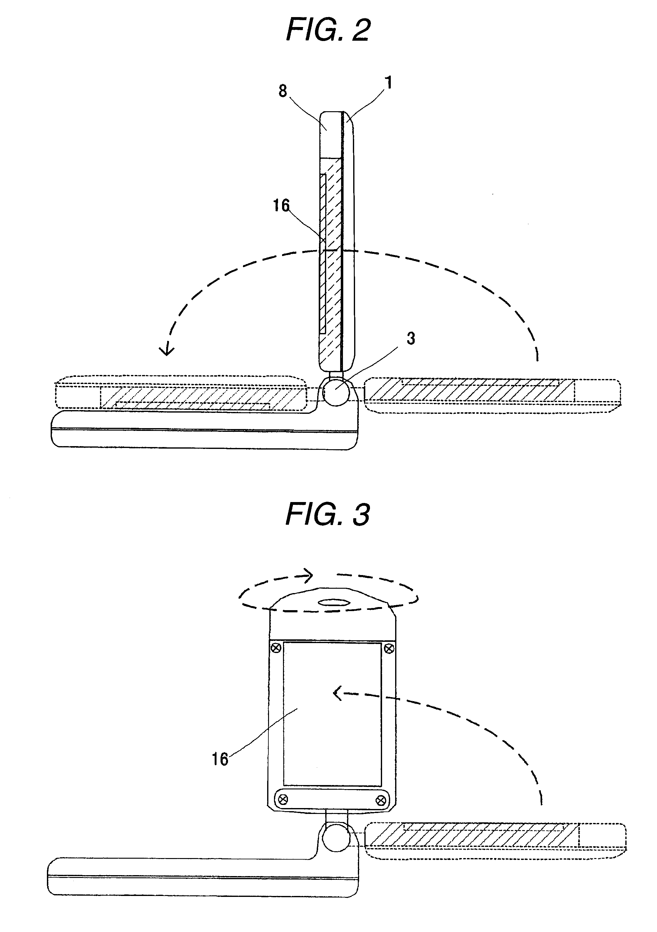
[0059]The hinged part 3 includes a rotation axis 4 and a rotation axis 5 whose rotating directions differ from each other. As shown in FIG. 2, the upper housing is rotated about the rotation axis 4 to place the cell phone in the state where the housings are unfolded or the state where the housings are folded. As shown in FIGS. 3 and 4, when the upper housing is rotated by 180 degre...

second embodiment

[0102]FIG. 10 shows a basic configuration of a cell phone equipped with a broadcast receiver according to the second embodiment of the invention. In FIG. 10, a component given a same sign as FIG. 1 performs the same operation and thus detailed description of such a component is omitted.

[0103]In FIG. 10, on top of the configuration shown in FIG. 1, a high frequency switch 28 is inserted between a loop element 12 and a matching circuit 12.

[0104]When the high frequency switch 28 is turned OFF, the loop element 12 is open and its resonance frequency shifts to an extremely high frequency. In the closed state shown in FIG. 5 or FIG. 6, in case the loop element 12 is open as described above, the electromagnetic interaction between the loop element 12 and a monopole element 19 becomes small and the performance degradation caused by the presence of the loop element 12 is suppressed to a very low level.

[0105]Taking advantage of this, a control part 29 may detect that the cell phone is in the ...

third embodiment

[0111]FIG. 11 shows a basic configuration of a cell phone equipped with a broadcast receiver according to the third embodiment of the invention. In FIG. 11, a component given a same sign as FIG. 1 performs the same operation and thus detailed description of such a component is omitted.

[0112]The cell phone equipped with a broadcast receiver shown in FIG. 11 includes a fold-down meander antenna 30 for reception of broadcasts on top of the configuration shown in FIG. 1. FIG. 11 shows a viewer state where the user may watch a display part 16.

[0113]The fold-down meander antenna 30 is rotatably supported by a rotation axis 31 in close proximity to the hinged part of a lower housing 2. The fold-down meander antenna 30 rotates about the rotation axis 31 to extend the fold-down meander antenna 30 out of the housing as shown in FIG. 11 or to house the fold-down meander antenna 30 inside the perimeter of the housing.

[0114]The fold-down meander antenna 30 is arranged in close proximity to a hin...


PUM


Abstract

To provide a cell phone equipped with a broadcast receiver that delivers a high receiving sensitivity and antenna performance in various usage states.
A loop element 12 as an antenna for receiving television broadcast is arranged in a range (c) of an upper end portion of an upper housing 1. An end part of an upper circuit board is matched with a portion shown by (a) so that a conductor other than the antenna element does not exist in the range (c). A monopole element 19 for cell phone communication is arranged at a lower end portion of a lower housing 2.

Description

TECHNICAL FIELD[0001]The present invention relates to a broadcast receiving antenna housed in a cell phone equipped with a feature to receive broadcasts such as a television broadcast.BACKGROUND ART[0002]As a broadcast receiving antenna equipped with a television broadcast receiving feature, there is known a configuration using a loop antenna such as one described in JP-A-10-084209.DISCLOSURE OF THE INVENTION[0003]In case the related antenna described in JP-A-10-084209 is housed in a clamshell cell phone having a structure where the upper and lower housings can be folded about a hinge as an axis, an antenna element housed in either housing is in proximity to a conductor having a ground potential such as a circuit board or a shield case in the other housing when the cell phone is folded, thus resulting in lower antenna performance and degraded receiving sensitivity.[0004]A compact-size broadcast receiving antenna housed in a small cell phone shows a reduced radiation resistance, narr...

Claims


Application Information

Patent Timeline
IPC IPC(8): H04M1/00
CPCH01Q1/084H01Q1/243H01Q1/36H01Q7/00H04N2007/145H01Q21/28H04N7/142H04N7/147H01Q9/42
Inventor YAMAZAKI, YUKARIKOSHI, MASASHIKAKITSU, HARUHIKOHASHIGAYA, ATSUHIKOSASAKI, HIROYUKISAITO, YUTAKANAGANO, KENYA
Owner PANASONIC CORP
Why Eureka
Try Eureka