Configuring and using multi-dimensional zones

a multi-dimensional zone and configuration technology, applied in the field of monitoring wireless devices, can solve the problems of not necessarily providing a precise location, current systems are limited to relaying gps information,

Active Publication Date: 2009-05-21
WIRELESSWERX IP LLC
View PDF100 Cites 127 Cited by
  • Summary
  • Abstract
  • Description
  • Claims
  • Application Information

AI Technical Summary

Benefits of technology

[0008]Previous systems have been developed to attempt to locate a wireless communication device utilizing wireless access points and routers. For example, the wireless communication device could be in a location having several buildings in range of the wireless communication device. However, these systems do not necessarily provide a precise location. In another situation, the wireless communication device may be in a building with several floors, each floor having its own location node. In this situation, the wireless communication device may be closer to a location node on a different floor.
[0009]The present disclosure relates to an apparatus, system, and method for defining a three-dimensional geographical zone utilized with a movable entity having at least one attached transponder. The method comprises allowing a user to enter at least one waypoint, and loading at least one waypoint on at least one transponder. In one or more embodiments, a waypoint is defined by a geographical coordinate and a radius. The geographical coordinate is represented by a latitude value, a longitude value, and an elevation value. And, the radius is represented by a distance magnitude. The area that the waypoint defines is a circle, a cylinder, or a sphere.

Problems solved by technology

Current systems are limited to relaying the GPS information to a control center or a web server and plotting the position of the person or vehicle on a computer map.
However, these systems do not necessarily provide a precise location.

Method used


Image

  • Configuring and using multi-dimensional zones
  • Configuring and using multi-dimensional zones
  • Configuring and using multi-dimensional zones

Examples


Embodiment Construction

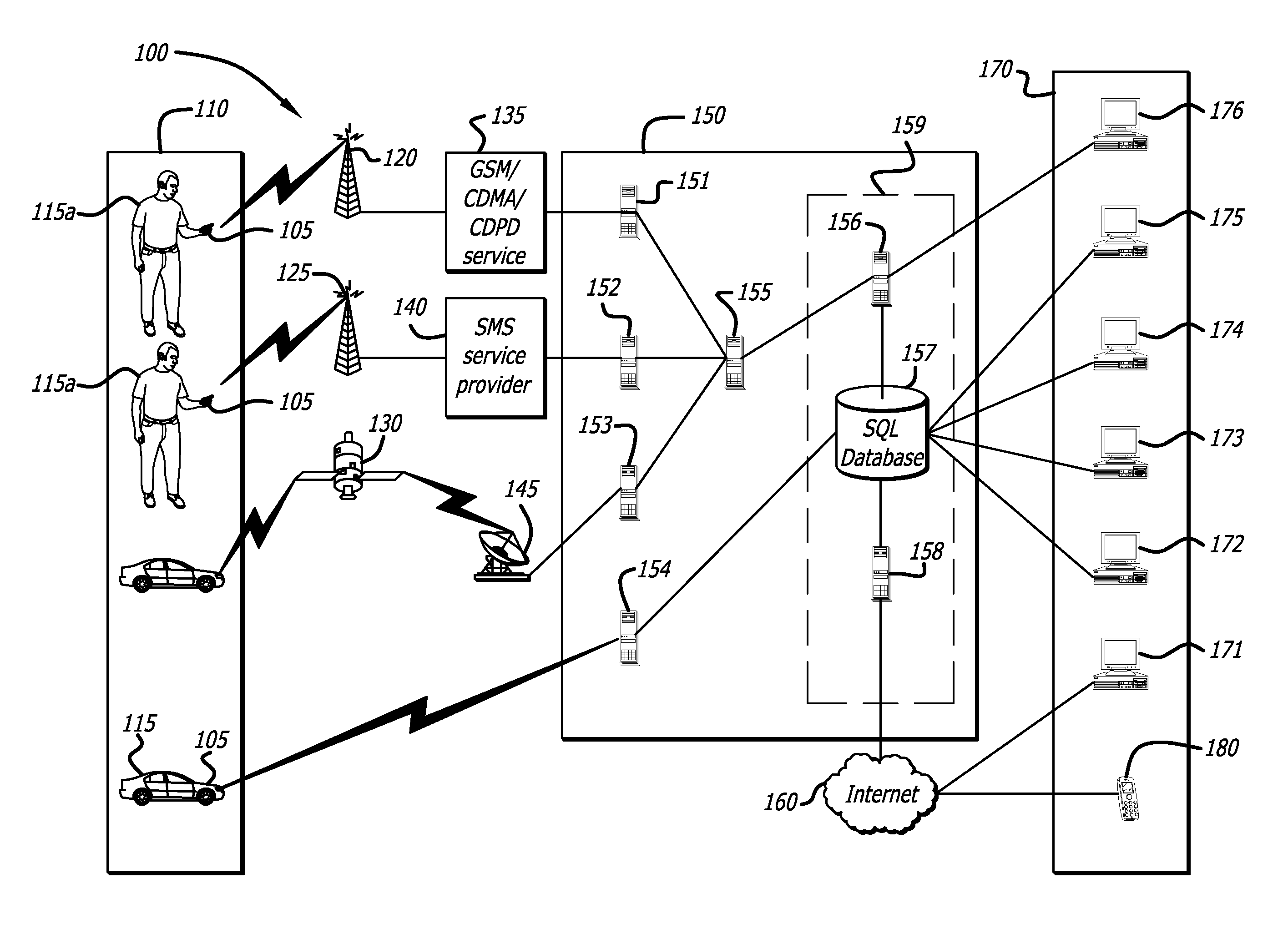
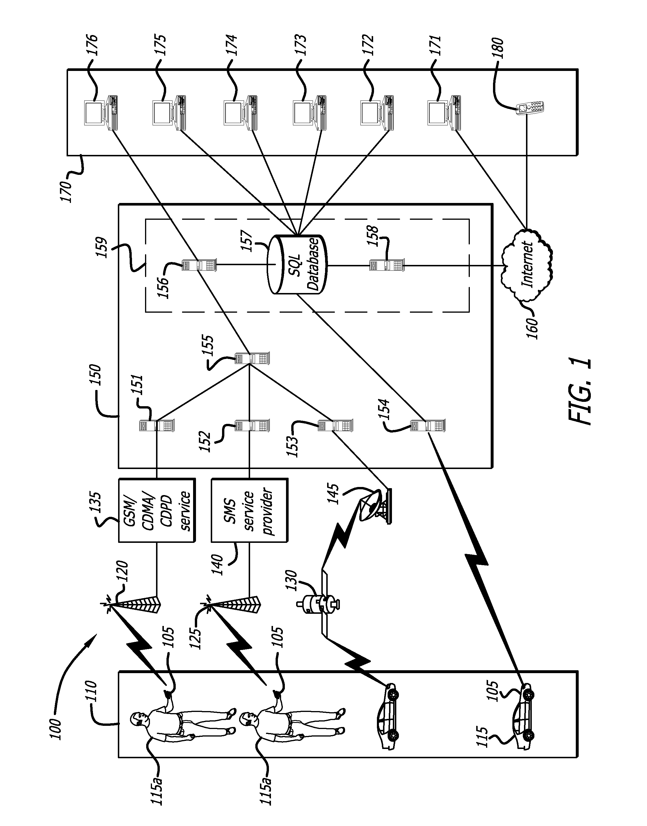
[0037]The present disclosure provides a system and method that allows a user to control and monitor individuals, vehicles and other movable entities by using geographical zones. These zones can be pre-configured geographical zones. Such zones have a plurality of nodes. In different situations, messages can be sent between one or more of these mobile users and one or more control stations. The users can be a single user or multiple users in a group with whom there are message communications. The messages can be targeted to the one or multiple users.

[0038]The multi-dimensional sense can be a three-dimensional sense in the x, y and z axes or coordinates. The system allows for three-dimensional mapping according to the placement of nodes in a three-dimensional sense. Further messages can be communicated with movable entities according to their location in the three-dimensional space, and the messages may be commercial or emergency messages.

[0039]The nodes are preferably part of a mesh n...


PUM


Abstract

A method to define a three-dimensional geographical zone that is utilized with a movable entity having at least one attached transponder is disclosed. The method comprises allowing a user to enter at least one waypoint, and loading at least one waypoint on at least one transponder. In one or more embodiments, a waypoint is defined by a geographical coordinate and a radius. The geographical coordinate is represented by a latitude value, a longitude value, and an elevation value. And, the radius is represented by a distance magnitude. In some embodiments, the method further comprises regulating the movable entity by monitoring, controlling, and/or visualizing the movement, non-movement, or position of the movable entity. The transponder determines whether the transponder is located inside the three-dimensional geographical zone by obtaining global positioning coordinates, and calculating whether or not the global positioning coordinates are located inside at least one waypoint.

Description

CROSS REFERENCE TO RELATED APPLICATIONS AND PATENTS[0001]This application is a Continuation in Part of U.S. patent application Ser. No. 11 / 848,178, filed Aug. 30, 2007, and claims the benefit of the prior filing date of U.S. Provisional Patent Application Ser. No. 60 / 625,467, filed Nov. 5, 2004. These applications are incorporated by reference in their entirety. This application is related to U.S. patent application Ser. No. 12 / 044,840, filed Mar. 7, 2008, which is incorporated by reference in its entirety.BACKGROUND[0002]1. Field of the Disclosure[0003]This application relates generally to monitoring wireless devices and to messaging by wireless communication between wireless devices in a specific geographical location and remote centers.[0004]The disclosure also relates to configuring and using geographical zones in multi-dimensional spaces. In particular, it relates to systems and methods to remotely control and monitor movable entities, their functions and to positioning data in...

Claims


Application Information

Patent Timeline
Patent Type & Authority Applications(United States)
IPC IPC(8): G01C21/00
CPCG01S5/0045G01S13/878H01Q1/243G08G1/205G08G1/207G07C9/00111G07C9/28
Inventor ASHLEY, JR., JAMESMOONEY, PATRICK
Owner WIRELESSWERX IP LLC
Why Eureka
Try Eureka