Method for Controlling or Regulating the Air Pressure in a Compressed Air Supply Device

Inactive Publication Date: 2009-05-28
KNORR-BREMSE SYST FUER NUTZFAHRZEUGE GMBH
5 Cites 8 Cited by

AI-Extracted Technical Summary

Problems solved by technology

One disadvantage to be noted in this regard is that any action of the pressure controller entails compressed air losse...

Benefits of technology

[0010]There may likewise be provision for the decrease in the efficiency of the air filter unit with the running time of the air filter unit to be taken into account in the calculation of the moisture value. Without the running time behavior being taken into account, an efficiency which is ...

Abstract

A method is provided for controlling and/or regulating the air pressure in a compressed air supply device for a utility vehicle. At least one pressure value in the compressed air supply device and/or in vehicle components connected to the compressed air supply device is recorded. A humidity value representing the humidity content in an air filter unit associated with the compressed air supply device is determined. A clutch connecting a drive to a compressor is opened. A discharge valve of the compressed air supply device is opened when the pressure value is above a predetermined minimum value and the humidity value exceeds a predetermined threshold value. The clutch is opened and the discharge valve remains closed when it is indicated that the clutch can be engaged, the pressure value reaches a predetermined cutting-off pressure, and the humidity value is below the predetermined threshold value.

Application Domain

Technology Topic

Image

  • Method for Controlling or Regulating the Air Pressure in a Compressed Air Supply Device
  • Method for Controlling or Regulating the Air Pressure in a Compressed Air Supply Device
  • Method for Controlling or Regulating the Air Pressure in a Compressed Air Supply Device

Examples

  • Experimental program(1)

Example

DETAILED DESCRIPTION OF THE DRAWINGS
[0023]In the following description of the drawings, the same reference symbols designate identical or comparable components.
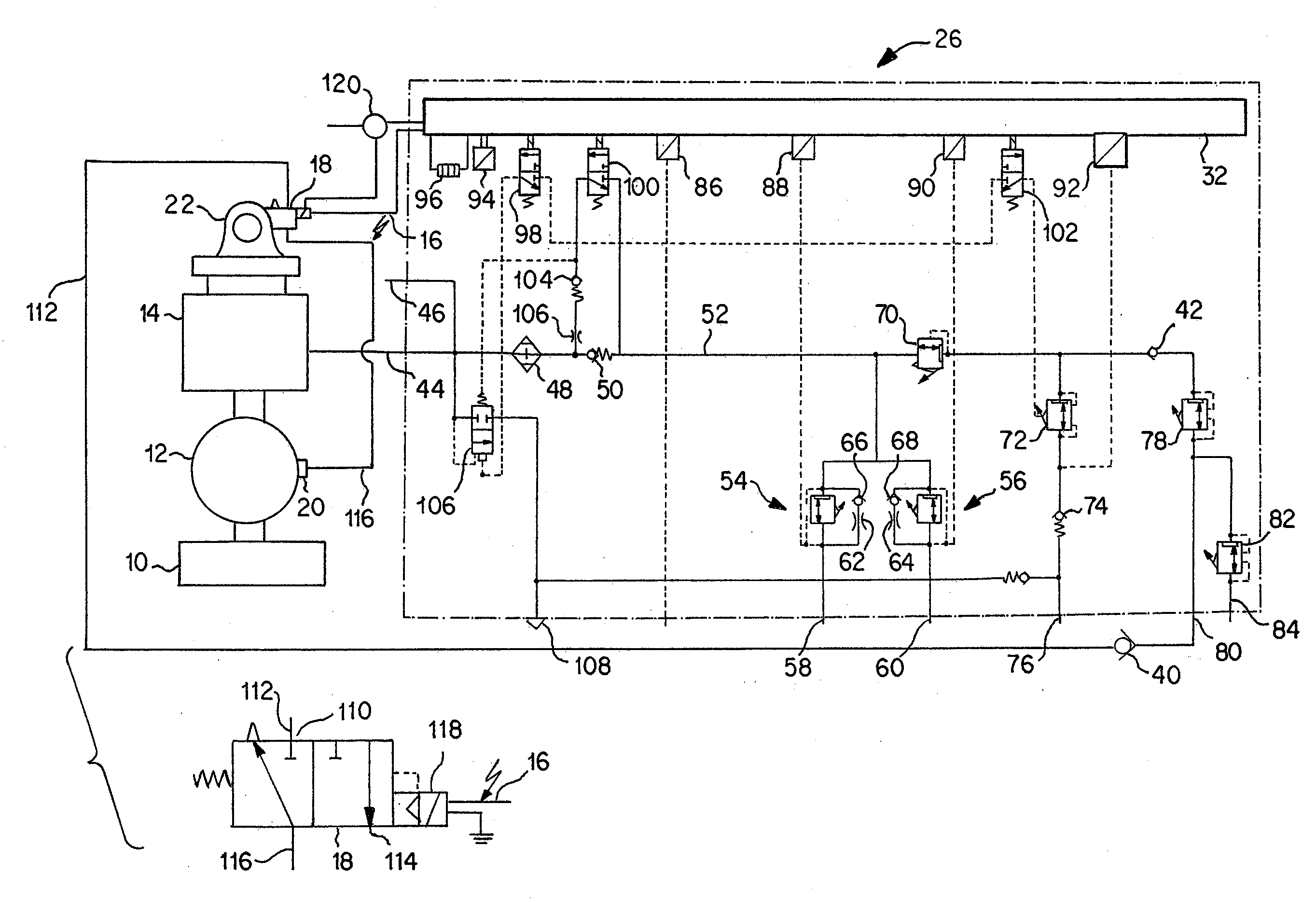
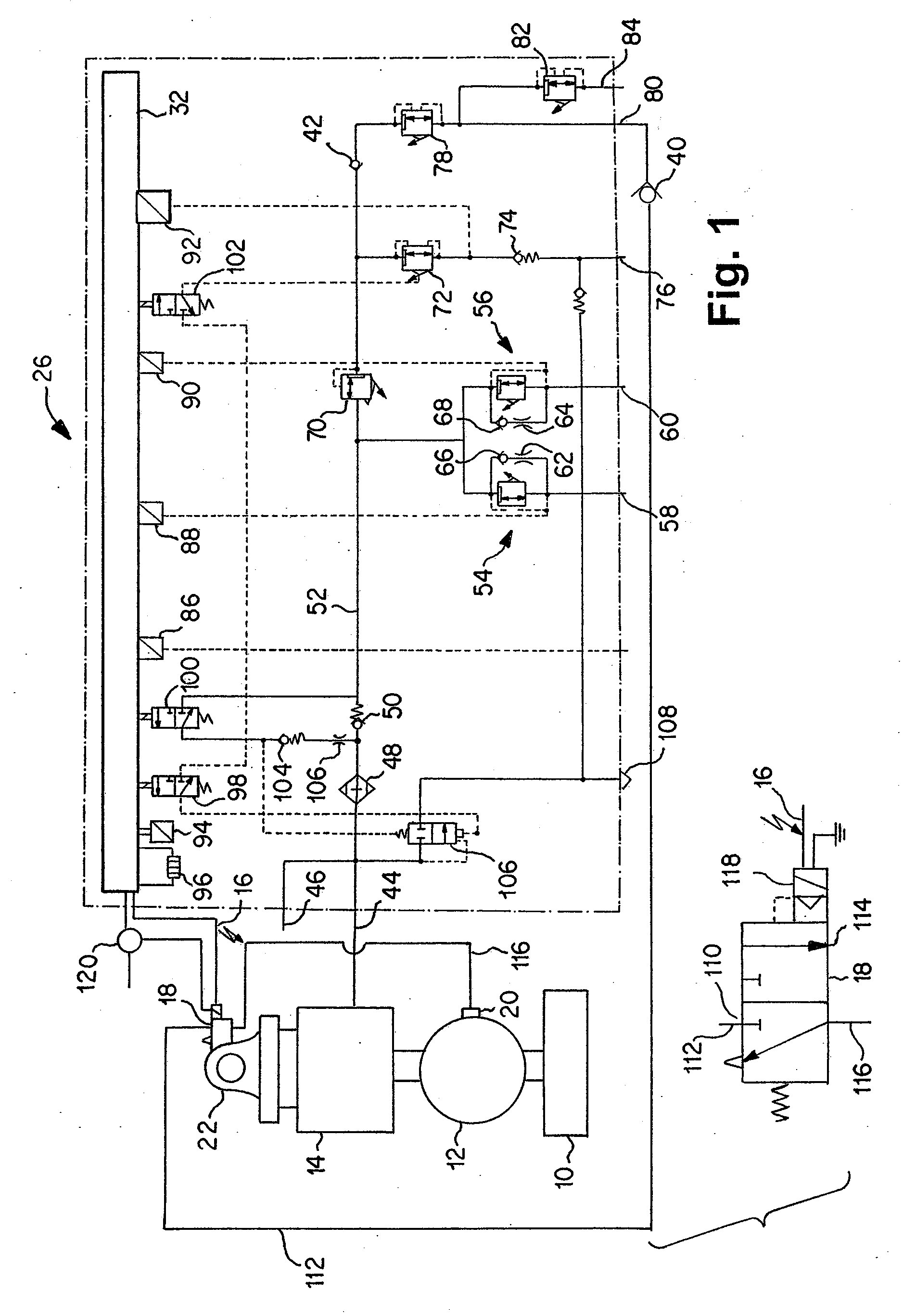
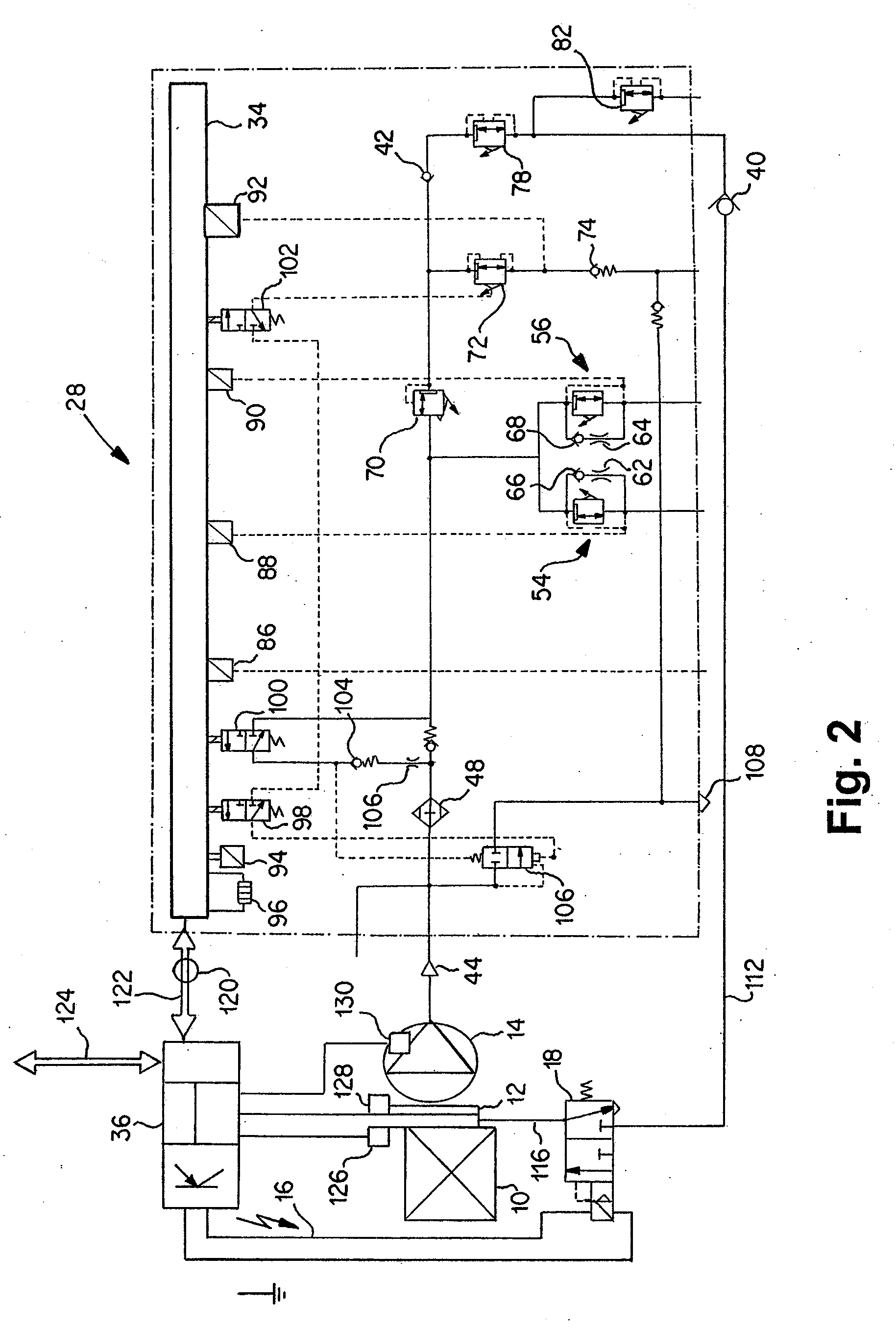
[0024]FIG. 1 shows a diagrammatic illustration of a compressed air supply device according to the invention. A compressed air preparation plant 26 is illustrated. By means of this, compressed air supplied is filtered and is distributed to various compressed air consumers. An inlet connection 44 is provided, which is connected to a compressor 14 provided outside the compressed air preparation plant 26. An extraneous filing connection 46 is arranged parallel to the inlet connection 44. The compressed air supplied to one of the inlets 44, 46 is supplied to a filter unit 48 and from there, via a nonreturn valve 50, to a main supply line 52. Arranged in parallel on the main supply line 52 are two overflow valves 54, 56, via which connections 58, 60 for the service brake circuits of the utility vehicle are supplied with compressed air. A throttle 62, 64 and a nonreturn valve 66, 68 are arranged in each case parallel to the overflow valves, according to the present embodiment a flow, parallel to the flow through the overflow valves 54, 56, from the main supply line 52 to the connections 58, 60 of the service brake circuits being made possible. As a result, particularly during the refilling of the system, even in the case of low pressures in the main supply line 52, an early filling of the service brake circuit reservoirs can take place. It is likewise possible to provide the nonreturn valves in the opposite direction, this refilling benefit being dispensed with. A refilling of secondary consumers from the reservoirs of the service brake circuits is then made possible as a result. Furthermore, a pressure limiter 70 is provided in the main supply line 52. Two further lines branch off in parallel on the pressure-limited side of the pressure limiter 70, a connection 76 for the parking brake and the trailer brake system being supplied by means of one line via an overflow valve 72 and a nonreturn valve 74. The other line, via a nonreturn valve 42 and an overflow valve 78, feeds a connection 80 which is provided for actuating the compressor clutch 12. The overflow valve 78 is followed in a branching-off line by a further overflow valve 82 via which a further secondary consumer connection 84 is supplied.
[0025]A plurality of pressure sensors 86, 88, 90, 92 are connected to the electronic control 32, the pressure sensor 88 measuring the pressure at the service brake connection 58, the pressure sensor 90 measuring the pressure at the service brake connection 60 and the pressure sensor 62 measuring the pressure directly downstream of the overflow valve 72 for the connection 76 of the parking brake and trailer. Furthermore, a temperature sensor 94 and a heating 96 are connected to the electronic control 32. Moreover, three solenoid valves 98, 100, 102 are connected to the electronic control 32: the pressure controller solenoid valve 98, the regeneration solenoid valve 100 and a solenoid valve 102 for the additional pressure control of the overflow valve 72. The solenoid valves 78, 100, 102 are designed as 3/2-way valves and are all closed in the currentless state. In the closed state, the pressure of the main supply line 52 is present at the inputs of the solenoid valves 98, 100, 102. To initiate a regeneration operation, it is necessary to apply current to the regeneration solenoid valve 100 and the pressure controller solenoid valve 98 and thus transfer them into their state not illustrated. The result of this is that dry compressed air is extracted from the service brake reservoirs via the main supply line 52 and then, bypassing the nonreturn valve 50, flows through the filter unit 48 in the opposite direction via the regeneration solenoid valve 100, a further nonreturn valve 104 and a throttle 106, in order then to flow via a discharge valve 106, changed over into its switching position, not illustrated on account of the changeover of the pressure controller solenoid valve 98, to a discharge 108 and from there out into atmosphere. The compressor 14 already mentioned, an internal combustion engine 10 and a shiftable clutch 12 connecting the compressor 14 to the internal combustion engine 10 are illustrated outside the compressed air preparation plant 26. The compressor 14 has an intake connection piece 22, via which the air to be compressed is sucked in. In the region of this air supply, a 3/2-way valve 18 is arranged, which in the present case is designed as an electrically pilot-controlled pneumatic valve, as is also illustrated separately. The pneumatic valve 18 has an inlet connection 110 to which a line 112 leading to the clutch connection 80 is connected. In this line 112, a nonreturn valve 40 is arranged, which permits a flow from the clutch connection 80 to the valve 18 and prevents a reverse flow. The valve 18 has an outlet connection which is coupled to a shift input 20 of the clutch 12 via a line 116. Via an electrical input 118 for the purpose of supplying a signal 16, the valve is connected to the electronic control 32 of the compressed air preparation plant 26 and to a ground which is picked off at a central plug 120.
[0026]The compressed air supply device according to FIG. 1 operates as follows in terms of the shiftable clutch 12. When the clutch 12, closed in the non-pressure-activated state, is to be opened, the electronic control 32 sends an output signal 16 to the electrically pilot-controlled pneumatic valve 18. The valve 18 opens, and a connection is thereby made between the clutch connection 80 of the compressed air preparation plant 26 and the shift input 20 of the clutch 12. As a result of the pneumatic activation of the shift input 20, the clutch 12 is opened. When a regeneration of the filter unit 48 is to take place, the pressure controller solenoid valve 98 and the regeneration solenoid valve 100 are changed over, so that the discharge valve 106 opens and dry air can flow out of the consumer-side reservoirs in the opposite direction through the filter unit 48, the discharge valve 106 and the discharge 108 into the open. If regeneration is not required, however, the solenoid valves 98, 100 remain in the closed state. The opening of the clutch 12 then alone assumes the pressure controller function. To close the clutch 12, the application of current to the electric input 118 is discontinued again, so that the shift input 20 is vented. A short switching time is ensured by means of the nonreturn valves 40, 42. The nonreturn valve 42 prevents a backflow of compressed air out of the line 112 in the direction of the branches of the service brake connections 58, 60 and the connection for the parking brake and the trailer. The nonreturn valve 40 additionally prevents a backflow out of the line 112 to the secondary consumer connection 84. Depending on the design of the plant and the requirements as regards the switching time, one of the nonreturn valves 40, 42 may be sufficient. The nonreturn valves 40, 42 thus ensure that a certain pressure level can always be maintained in the intact line 112, so that, during the changeover of the valve 18, a rapid pressure build-up at the shift input 20 of the compressor 14 is ensured. An additional reservoir in the region of the line 112, by means of which reservoir the maintaining of such a pressure level could likewise be ensured, is therefore unnecessary.
[0027]FIG. 2 shows a diagrammatic illustration of a compressed air supply device according to the invention. Many properties of the embodiment according to FIG. 2 are identical to the embodiment according to FIG. 1, for example also the preferred arrangement of the electrically pilot-controlled pneumatic valve 18 in the region of the air inlet of the compressor 14, even though this is not illustrated here. In contrast to the embodiment according to FIG. 1, in the embodiment according to FIG. 2 an external control 36 is provided, in addition to the electronic control 34, in the compressed air preparation plant 28. The external control 36 is suitable for communicating with the internal control 34 via an interface 122 which is preferably made available by the central plug 120. An interface 124 with other vehicle components is likewise provided, for example with a vehicle management computer via a CAN bus. The interfaces 122, 124 may be combined in structural terms. Furthermore, it is shown in FIG. 2 that a rotational speed sensor 126 may be arranged on the input side of the clutch 12 and a further rotational speed sensor 128 may be arranged on the output side of the clutch 12. Moreover, a temperature sensor 130 is provided on the compressor 14. The signals from the sensors 126, 128, 130 are delivered to the external control 36 and are taken into account by the latter with regard to the activation of the valve, or are evaluated in another way, for example with regard to function monitoring, and/or are transferred in original or processed form via the interfaces 122, 124.
[0028]The useful determination of the rotational speeds and of the temperature may also be provided in connection with the embodiment according to FIG. 1, even though this is not illustrated here. The corresponding data are then delivered to the internal control 32 of the compressed air preparation plant 26.
[0029]FIG. 3 shows a diagrammatic illustration of a compressed air supply device according to the invention. The compressed air supply device illustrated here is illustrated in the form of a plurality of distributed individual subassemblies. In particular, a pressure controller 130 with an attached filter unit 48, a multiple-circuit protection valve 132, pressure limiters 134, 136 and an electronic control 38 are illustrated. The components may in reality be distributed in the way described. However, the distributed illustration may also be understood in the sense of a functional division, the pressure regulator, multiple circuit protection valve, pressure limiters and/or electronic control in reality being implemented in integrated forms, for example as illustrated in connection with FIGS. 1 and 2.
[0030]In the embodiment according to FIG. 3, once again, a compressor 14 is coupled to an internal combustion engine 10 via a shiftable clutch 12. The compressor 14 delivers compressed air to the pressure controller 130, from where the compressed air is transferred to the multiple-circuit protection valve 132. The multiple-circuit protection valve 132 distributes the compressed air to the reservoirs 138, 140 and other connections, one of which is illustrated as a connection provided with a pressure limiter 136. A further connection is the clutch connection 80, likewise supplied via a pressure limiter 134. Compressed air is delivered to the electrically pilot-controlled pneumatic valve 18 from the clutch connection 80 via the nonreturn valve 40 ensuring the switching times. The activation of the valve 18 takes place by means of the electronic control 38 which likewise communicates with the internal combustion engine or with an engine control via the interface 124. The electronic control 38 has a plurality of inputs 142, 144, 146. The inputs 142, 144 symbolize the possibility of supplying the control 38 with temperature, pressure and/or rotational speed information, for example measured by the pressure sensors 88, 90 of the service brake circuits and/or by the rotational speed sensors 126, 128 on the input side and the output side of the clutch 12. On the pressure controller 130, a pressure switch 24 is provided. This is connected to the input 146 of the electronic control 38. A pressure-dependent electrical signal can therefore be supplied to the electronic control 38.
[0031]The compressed air supply device according to FIG. 3 operates as follows. On the basis of the information made available via the inputs 142, 144, 146 and the interface 124, the electronic control 38 can deliver an electrical signal 16 to the valve 18, so that the latter changes over and opens the clutch 12 by virtue of the ventilation of the shift input 20. The decision to output the signal 16 may then be made on the basis that pressures, temperatures or rotational speeds measured by sensors make it necessary to open the clutch 12. In parallel with this, however, the opening of the clutch may also take place on the basis of the signal output by the pressure switch 24. If components of the embodiment illustrated in FIG. 3 experience a defect, so that, for example, the pressure levels in the service brake circuits are no longer measured reliably, the presence of the pressure switch 24 and of the switch functionality thereby made possible nevertheless makes it possible for the clutch 12 to be opened, thus preventing the destruction of the latter on account of the defects outlined.
[0032]In addition to the variant illustrated in FIG. 3, it is likewise possible to supply the output signal from the pressure switch 24 directly to the valve 18, so that, even in the event of a complete failure of the electronic control 38, an opening of the clutch 12 can take place.
[0033]FIG. 4 shows a flow chart for explaining a method according to the invention. In a step S01, the system pressure is detected, for example in the region of the service brake circuits. In a step S02, the moisture content in the air filter unit is determined, either by measurement or by calculation on the basis of the air volume conveyed by the compressor, the compressor rotational speed and the efficiency of the air filter unit. In step S03, it is determined whether the system pressure is higher than a predetermined switch-off pressure. If this is so, in step S04 the clutch is opened. In the opposite case, no opening of the clutch takes place, and the sequence returns to step S01. After the opening of the clutch in step S04, in step S05 a check is made as to whether the moisture value is higher than a predetermined threshold value. If this is so, in step S06 regeneration is initiated. If the moisture value is not higher than the threshold value, further monitoring and control functions may take place according to step S07, just as they can after regeneration according to step S06.
[0034]It should be noted that the flow chart according to FIG. 4 illustrates only a partial aspect of the monitoring in terms of the system pressure and the moisture content. For example, a check as to whether the moisture value is higher than the threshold value is also carried out irrespective of whether the switch-off pressure is present. Regeneration is also carried out at lower pressures if the system pressure is higher than the minimum pressure.
TABLE OF REFERENCE SYMBOLS
[0035] 10 Drive [0036] 12 Clutch [0037] 14 Compressor [0038] 16 Signal [0039] 18 Valve [0040] 20 Shift input [0041] 22 Fresh air supply [0042] 24 Pressure switch [0043] 26 Compressed air preparation plant [0044] 28 Compressed air preparation plant [0045] 30 Compressed air preparation plant [0046] 32 Electronic control [0047] 34 Electronic control [0048] 36 Electronic control [0049] 38 Electronic control [0050] 40 Nonreturn valve [0051] 42 Nonreturn valve [0052] 44 Input connection [0053] 46 Extraneous filling connection [0054] 48 Filter unit [0055] 50 Nonreturn valve [0056] 52 Main supply line [0057] 54 Overflow valve [0058] 56 Overflow valve [0059] 58 Connection service brake circuit [0060] 60 Connection service brake circuit [0061] 62 Throttle [0062] 64 Throttle [0063] 66 Nonreturn valve [0064] 68 Nonreturn valve [0065] 70 Pressure limiter [0066] 72 Overflow valve [0067] 74 Nonreturn valve [0068] 76 Connection parking brake/trailer [0069] 78 Overflow valve [0070] 80 Connection clutch [0071] 82 Overflow valve [0072] 84 Connection secondary consumer [0073] 86 Pressure sensor [0074] 88 Pressure sensor [0075] 90 Pressure sensor [0076] 92 Pressure sensor [0077] 94 Temperature sensor [0078] 96 Heating [0079] 98 Solenoid valve [0080] 100 Solenoid valve [0081] 102 Solenoid valve [0082] 104 Nonreturn valve [0083] 106 Discharge valve [0084] 108 Discharge [0085] 110 Input connection [0086] 112 Line [0087] 114 Output connection [0088] 116 Line [0089] 118 Electrical input [0090] 120 Central plug [0091] 122 Interface [0092] 124 Interface [0093] 126 Rotational speed controller [0094] 128 Rotational speed controller [0095] 130 Pressure controller [0096] 132 Multiple-circuit protection valve [0097] 134 Pressure limiter [0098] 136 Pressure limiter [0099] 138 Reservoir [0100] 140 Reservoir [0101] 142 Input [0102] 144 Input [0103] 146 Input
[0104]The foregoing disclosure has been set forth merely to illustrate the invention and is not intended to be limiting. Since modifications of the disclosed embodiments incorporating the spirit and substance of the invention may occur to persons skilled in the art, the invention should be construed to include everything within the scope of the appended claims and equivalents thereof.

PUM

no PUM

Description & Claims & Application Information

We can also present the details of the Description, Claims and Application information to help users get a comprehensive understanding of the technical details of the patent, such as background art, summary of invention, brief description of drawings, description of embodiments, and other original content. On the other hand, users can also determine the specific scope of protection of the technology through the list of claims; as well as understand the changes in the life cycle of the technology with the presentation of the patent timeline. Login to view more.

Similar technology patents

Engine crankshaft

ActiveUS20160123379A1Decrease efficiencyEngine efficiency and therefore engine fuel economy be decreaseCrankshaftsConnecting rodsEngineeringCrankshaft
Owner:FORD GLOBAL TECH LLC

Fuel cell system

InactiveUS20150004513A1Decrease efficiencyFuel cell auxillariesAutomotive engineeringAnode
Owner:NISSAN MOTOR CO LTD

Switch device

ActiveUS20130112534A1Decrease efficiencySimple constructionTumbler/rocker switch detailsEngineeringElectrical and Electronics engineering
Owner:NITTEI MUSEN +1

Classification and recommendation of technical efficacy words

  • Decrease efficiency
  • Energy save

MIMO system and method

InactiveUS20060093060A1Increase in numberDecrease efficiencyDiversity/multi-antenna systemsError prevention/detection by diversity receptionEngineeringMulti input
Owner:SAMSUNG ELECTRONICS CO LTD

Programmable energy saving register vent

InactiveUS20070298706A1Energy saveReduce amount of energyDucting arrangementsMechanical apparatusLouverEngineering
Owner:SPRINGFIELD ACQUISITION CO LLC
Why Eureka
Try Eureka