
Dual inlet and dual outlet spa valve

a dual-inlet, spa valve technology, applied in multiple-way valves, mechanical equipment, transportation and packaging, etc., can solve the problems of achieve the effect of increasing the flow, increasing the water flow to the jets and the resulting turbulen

Inactive Publication Date: 2009-05-28
ELNAR JOSEPH G
View PDF11 Cites 9 Cited by
  • Summary
  • Abstract
  • Description
  • Claims
  • Application Information

AI Technical Summary

Benefits of technology

The present invention provides a valve that allows for increased flow in situations where space is limited. The valve has a cylindrical body with two inlets and two outlets, and a rotatable cylindrical plug that can be positioned to control the flow of water. The valve can be used in a spa to increase the water flow to the jets and create turbulence. The valve can be easily installed and maintained, and its unique design allows for the flow of water to be controlled without the need for a larger diameter pipe.

Problems solved by technology

The valve allows parallel pipes into the valve and from the valve to jets, thus increasing the water flow to the jets and the resulting turbulence.

Method used


Image

  • Dual inlet and dual outlet spa valve
  • Dual inlet and dual outlet spa valve
  • Dual inlet and dual outlet spa valve

Examples


Embodiment Construction

[0029]The following description is of the best mode presently contemplated for carrying out the invention. This description is not to be taken in a limiting sense, but is made merely for the purpose of describing one or more preferred embodiments of the invention. The scope of the invention should be determined with reference to the claims.

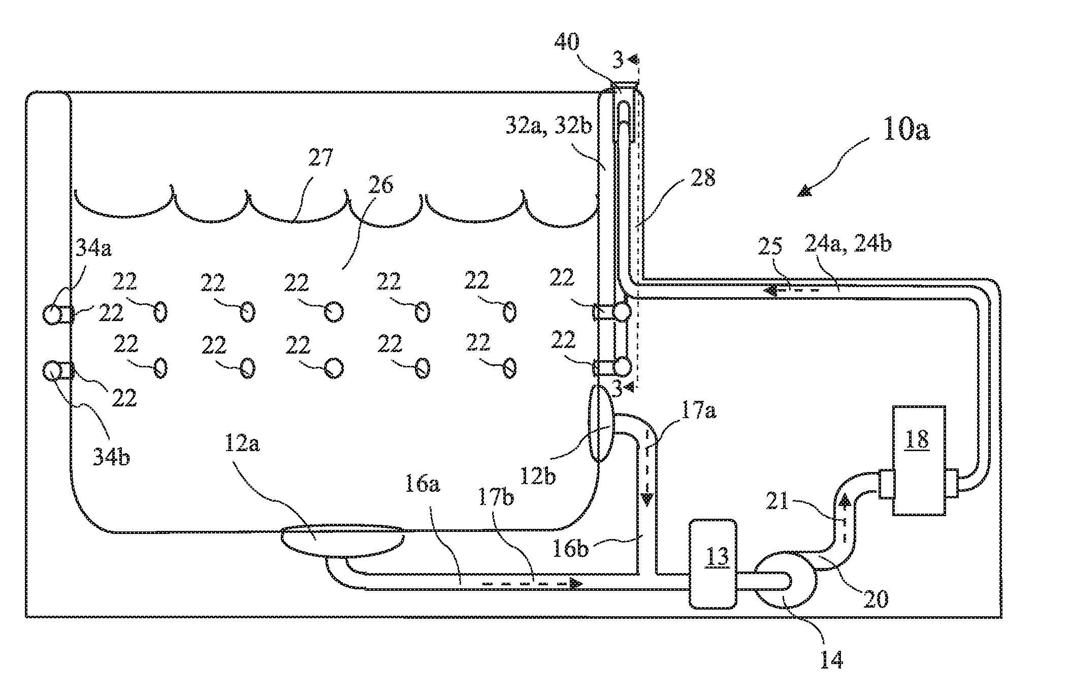
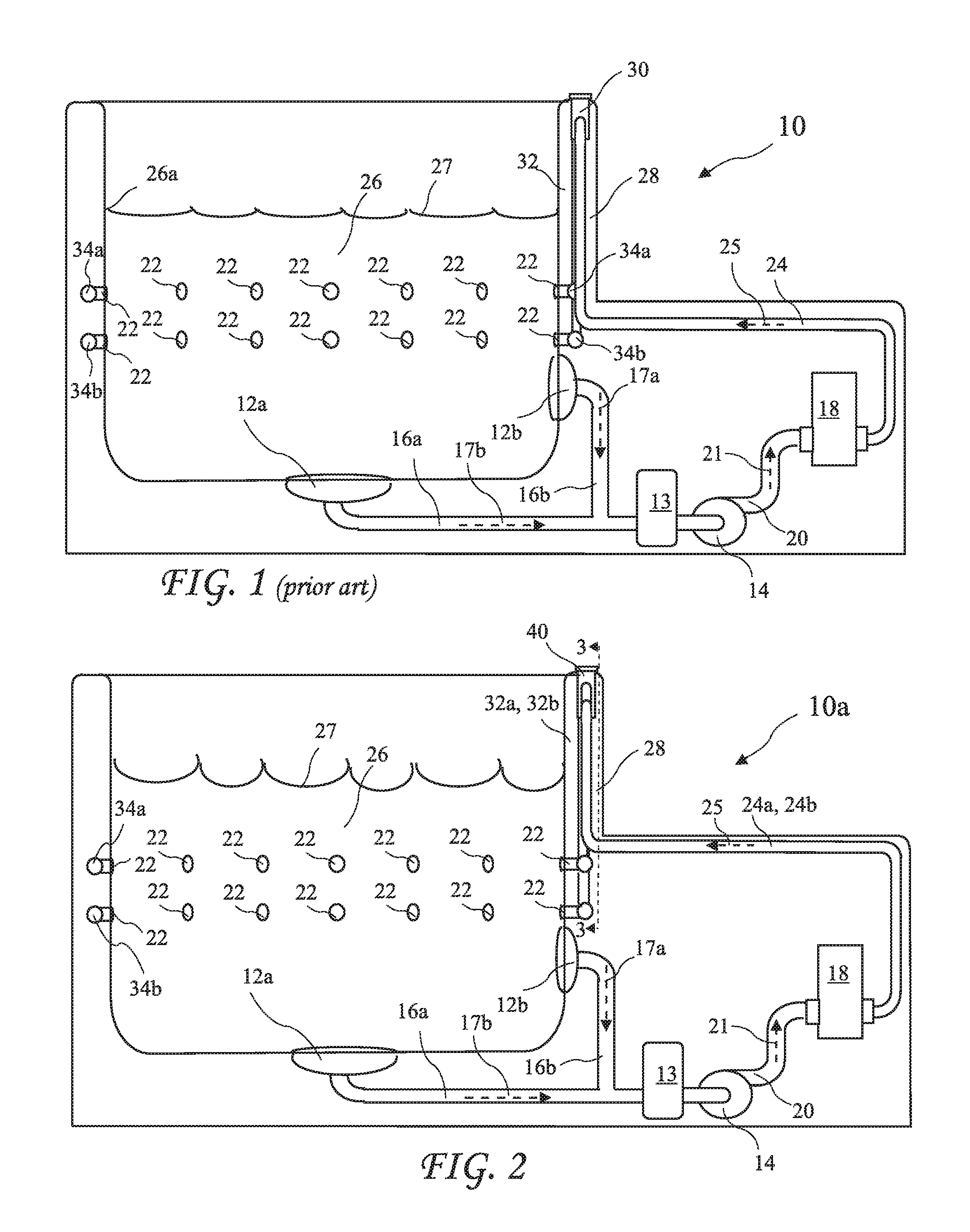
[0030]A prior art spa 10 is shown in FIG. 1. The spa 10 includes drains 12a and 12b. The drains 12a, 12b below a spa water line 26a are in fluid communication with a pump 14 through first pipes 16a and 16b carrying flows 17a and 17b of water 26 respectively, through a filter 13 and to the pump 14. A spa heater 18 is in fluid communication with the pump 14 through a second pipe 20 carrying second flow 21. The heater 18 is in fluid communication with jets 22 through inflow pipe 24, a valve 30, and an outflow pipe 32 carrying a heated flow 25 down to horizontal pipes 34a and 34b circling the spa and connected to the jets 22. The water is returned to ...


PUM


Abstract

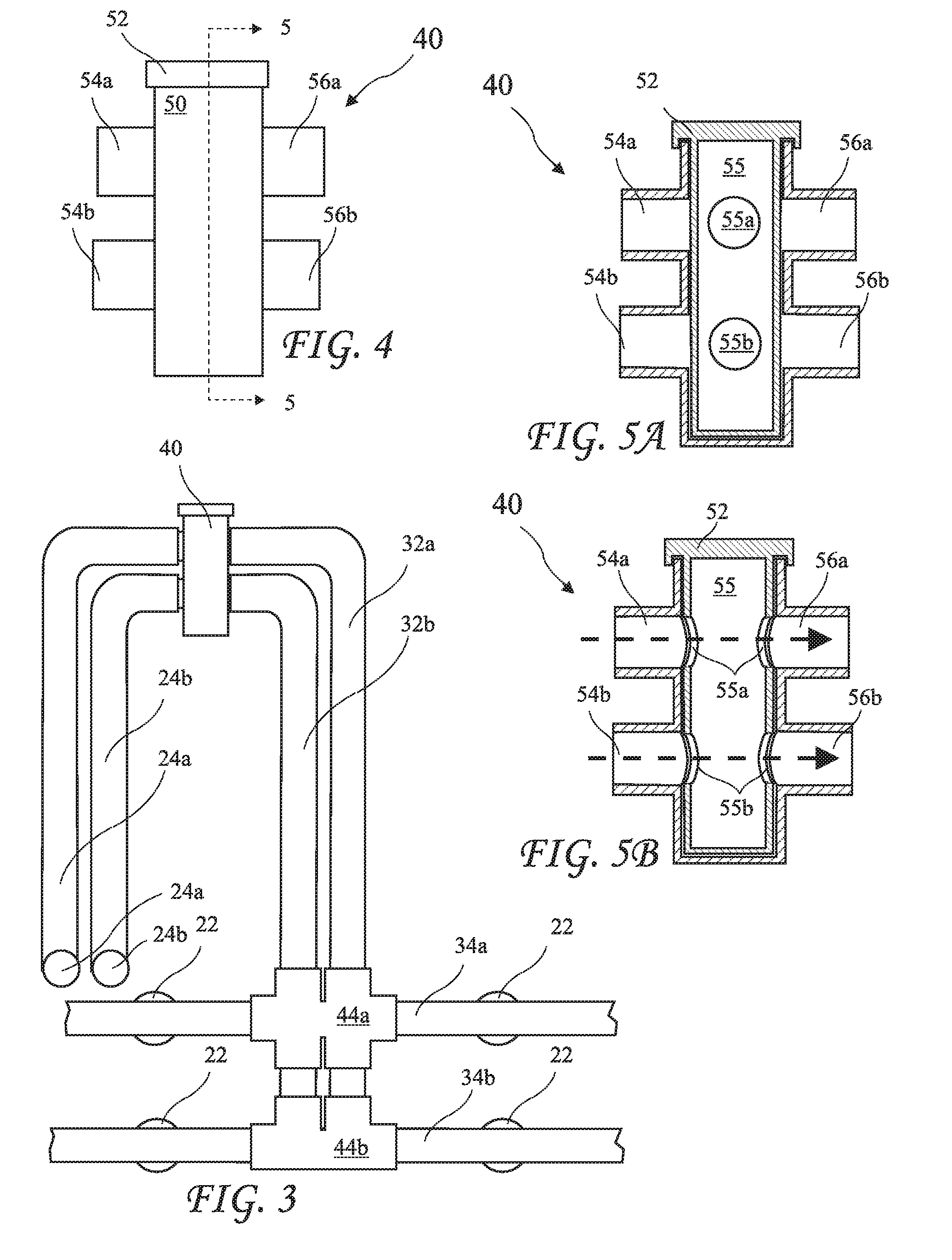
A dual inlet and dual outlet valve controls a flow from dual inlet pipes through dual outlets to dual outlet pipes to increase flow where space is not available for a single larger diameter pipe. The valve includes a rotatable cylindrical plug with vertically spaced apart plug mouths. The plug may be rotated to align the plug mouths with one of both dual outlets to allow a flow to the dual outlet pipes, or the plug may be rotated to block the flow to both outlets. The dual inlet and dual outlet valve is particularly useful in a spa where narrow spa walls limit pipe sizes. The valve allows parallel pipes into the valve and from the valve to jets, thus increasing the water flow to the jets and the resulting turbulence.

Description

BACKGROUND OF THE INVENTION[0001]The present invention relates to valves and in particular to spa valves.[0002]Home spas have become very common and are a source of relaxation and relief from stress encountered in everyday life. Such home spas generally include a spa tub and a pump / filter / heater unit for circulating water and jets for returning the circulated water to the spa. Spa owners generally expect the jets to produce substantial turbulence in the water and are often disappointed by the actual result. One solution to increasing turbulence is to increase the pump size. While a larger pump has a capability to increase flow and therefore the turbulence created by the jets, the flow is also limited by the pipes carrying the flow to the jets.[0003]Known spas have fairly thin spa walls. Given the insulation in the walls, there is only room for approximately two inch diameter pipes. This limitation on pipe size prevents taking full advantage of larger pumps.BRIEF SUMMARY OF THE INVEN...

Claims


Application Information

Patent Timeline
Patent Type & Authority Applications(United States)
IPC IPC(8): F16K11/00
CPCF16K11/0856Y10T137/86493
Inventor ELNAR, JOSEPH G.
Owner ELNAR JOSEPH G
Learn More