Flow back separators

a back separator and flow technology, applied in the direction of filtration separation, separation process, borehole/well accessories, etc., can solve the problems of reducing the efficiency of the separation process, limiting the energy available to separate solids from fluids, and damage components in downstream piping and processing equipment, so as to reduce the amount of stirring, and increase the energy for separating formation fluids

Inactive Publication Date: 2009-05-28
BOOTS & COOTS SERVICES
View PDF4 Cites 4 Cited by
  • Summary
  • Abstract
  • Description
  • Claims
  • Application Information

AI Technical Summary

Benefits of technology

[0006]Among other things, helical separators according to the present inventive principles, which apply centrifugal force to the formation fluid flow, advantageously provide more energy for separating formation fluids and solids compared to conventional gravity-only separators. In addition, by bringing the fluid flow into the separator through a horizontal inlet, the downward fluid velocity is reduced, which advantageously reduces the amount of stirring in the collection chamber and consequently the percentage of solids that exit the collection chamber through the separator and on to downstream processing equipment.

Problems solved by technology

Formation fluids being pumped from an oil or gas formation typically include unwanted solids, which can damage components in the downstream piping and processing equipment.
Because conventional separators essentially operate only using the force of gravity, the energy available to separate the solids from the fluids is limited, which in turn limits the effectiveness of the separation process.
Moreover, the downward fluid flow tends to stir the solids in the collection chamber, which also limits the percentage of the solids removed by the separator.

Method used


Image

  • Flow back separators
  • Flow back separators
  • Flow back separators

Examples


Embodiment Construction

[0018]The principles of the present invention and their advantages are best understood by referring to the illustrated embodiment depicted in FIGS. 1-2 of the drawings, in which like numbers designate like parts.

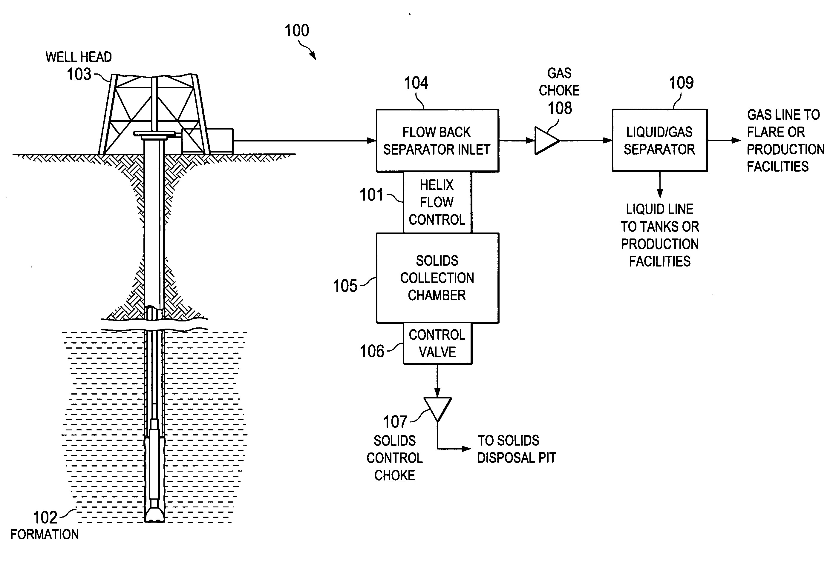
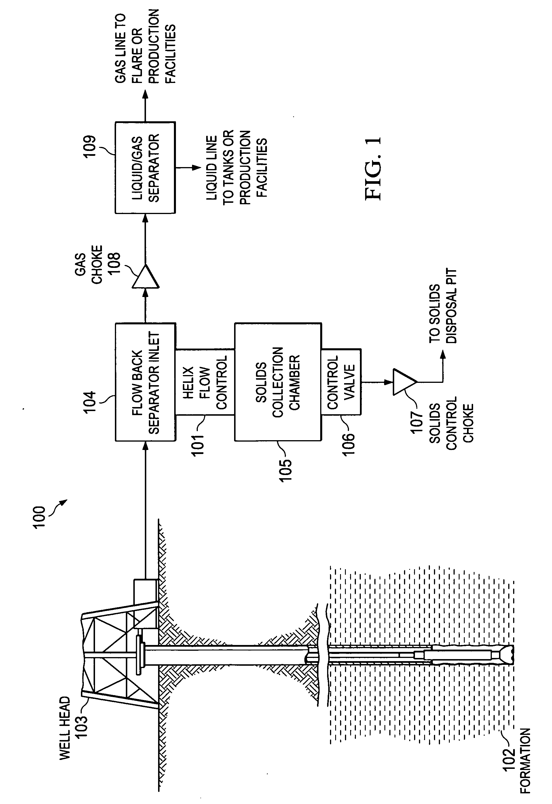
[0019]FIG. 1 is a high level diagram of a representative hydrocarbon extraction system 100 suitable for describing a typical application of the principles of the present invention, as embodied in helical flow back separator 101.

[0020]In system 100, formation fluids extracted from an underground formation 102 pass through the well head 103 and on to the flow back separator inlet 104. As discussed in detail below, according to the present inventive principles, helical flow back separator 101 receives the formation fluid flow through a horizontal (side) port and directs that flow along a downward helical path, which applies centrifugal force to the formation fluid flow. This centrifugal force separates the solids out of the formation fluids and forces the solids to the outer ho...


PUM

PropertyMeasurementUnit
centrifugal forceaaaaaaaaaa
angleaaaaaaaaaa
lengthaaaaaaaaaa

Abstract

A flow back separator including a housing including a bore housing for communicating with a solid collection chamber, an inlet port for receiving formation fluid flow, and a helical member disposed within the housing bore for directing formation fluid flow received through the inlet port along a helical path wherein solids within the formation fluid flow are forced towards a wall of the housing bore under centrifugal force.

Description

CROSS-REFERENCE TO RELATED DATA[0001]The present application claims the benefit of U.S. Provisional Patent Application Ser. No. 61 / 001,645, filed Nov. 2, 2007.FIELD OF INVENTION[0002]The present invention relates in general to hydrocarbon extraction equipment and in particular to flow back separators for removing solids from formation fluids.BACKGROUND OF INVENTION[0003]Formation fluids being pumped from an oil or gas formation typically include unwanted solids, which can damage components in the downstream piping and processing equipment. Hence it is important to remove these solids relatively soon after the formation fluids reach the surface. Normally solids are separated from formation fluids using flow back separators.[0004]All current flow back separator designs receive a flow of formation fluids, which continues into an underlying collection chamber where a percentage of the solids settle to the chamber bottom under the force of gravity. The formation fluids are then forced up...

Claims


Application Information

Patent Timeline
Patent Type & Authority Applications(United States)
IPC IPC(8): E21B43/00E21B21/06B01D33/27C02F1/38
CPCE21B43/34E21B43/35
Inventor SHACKELFORD, DONALD W.CLARK, MICHAEL L.HENDRIX, ROBERT T.HENDRIX, GLENDELL S.
Owner BOOTS & COOTS SERVICES
Why Eureka
Try Eureka